Skip to content

Klipper

3 posts with the tag “Klipper”

OrcaSlicer Calibration Masterclass: Pressure Advance — Which Test Do You Trust? (Part 3)
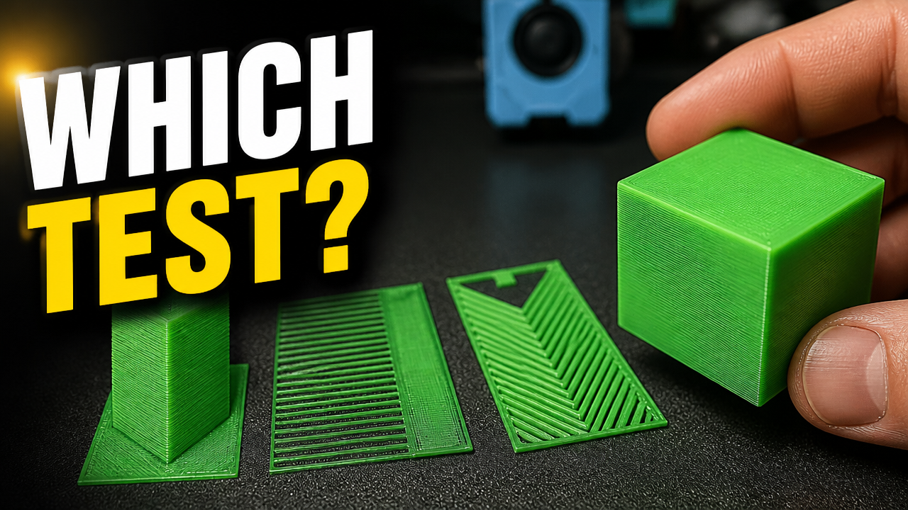
OrcaSlicer Pressure Advance Calibration Masterclass

Part 3 of the OrcaSlicer Calibration Masterclass is up, and this one’s about Pressure Advance — the setting responsible for those blobby corners and gapped lines that show up whenever your printer speeds up or slows down mid-print.

▶️ Watch on YouTube

Pressure Advance compensates for the lag between your extruder motor moving and the filament actually pushing out of the nozzle. When your printer accelerates, that lag shows up as bulging. When it decelerates, it shows up as gaps. Dial in the right PA value and the hot end pushes a consistent amount of filament out regardless of speed — sharp corners, no blobs, no gaps.

OrcaSlicer gives you three ways to find that value: the PA Tower, the PA Line test, and the PA Pattern test. I ran all three back to back on my Sovol SV08 (direct drive) to see how much they actually agree with each other.

TestValueNotes
PA Tower0.056Classic test, built into most slicers/firmware. Look for the sharpest corner.
PA Line0.054Fastest to read — look for the most consistent line.
PA Pattern0.050Newest test in OrcaSlicer, but I trusted this one least — the lines weren’t as clean on my print.

The three tests didn’t agree exactly, which is normal — they’re measuring the same thing with different amounts of visual noise. I ended up going with 0.055, splitting the difference between the Tower and Line results and discounting the Pattern test since I wasn’t confident in the read.

Once you’ve measured your test print, you still need to convert that measurement into an actual PA value — that’s the part most people get stuck on or get wrong by eyeballing it. I built a calculator that does this for you: plug in your start value, increment, and measured distance, and it gives you the number to paste into OrcaSlicer.

Pressure Advance Calculator →

Once you’ve got your number:

  1. Open your filament profile and hit Edit
  2. Scroll down and enable Pressure Advance
  3. Enter your calculated value
  4. Save the profile

That’s it — no firmware flashing, no macros, just a filament setting.

If you only have time for one test, run the Line test — it’s the fastest to print and read. If you want a second opinion (recommended, since no single test is perfect), add the Tower. I’d hold off on trusting the Pattern test alone until you’ve got some practice reading it — it’s more prone to misreads than the other two, at least in my experience.

For the full methodology straight from the source, OrcaSlicer’s own wiki has a good reference: OrcaSlicer Pressure Advance Calibration.

Part 4 covers Adaptive Pressure Advance — a more dynamic method that OrcaSlicer now recommends over the static single-value approach we used here. I’ll show you how to calculate and test it.

If you found this useful, the calculator hub has more tools like this — go.minimal3dp.com.

Questions about your own PA results? Drop them in the comments on the video or reach out directly.

OrcaSlicer 2.4 Beta: K2 Plus CFS Sync & Z-Contouring Deep Dive

Welcome back to the Minimal 3DP workbench. Today we are diving into the massive changes introduced in the OrcaSlicer 2.4 Beta release.

A quick personal note before we get to the technical data: I have not been posting as much lately due to struggles with anxiety and depression. I have gotten help and am doing much better. If you are struggling, please seek help; it benefits not only you, but everyone around you.

Now, let’s break down exactly what the 2.4 Beta brings to the table, where the current bugs lie, and how to optimize your hardware to take advantage of these new computational tools.


The Creality K2 Plus: CFS Filament Synchronization

Section titled “The Creality K2 Plus: CFS Filament Synchronization”

One of the most highly anticipated features in this beta is direct network synchronization for the Creality K2 Series CFS, the Color Filament System. For farm operators and enthusiasts using the K2 Plus daily, this is a massive workflow improvement.

However, because this is an early beta, the implementation is not without friction. During my testing, the initial synchronization attempt failed to connect.

If you experience a connection timeout when trying to sync your CFS to OrcaSlicer, try the following steps:

  1. Navigate to the device connection settings.
  2. Remove the specific port number from the end of your IP address string.
  3. Alternatively, use the Browse function to allow OrcaSlicer to auto-detect the Creality printer on your local network.
  4. If it still fails, restart OrcaSlicer. A fresh launch resolved the handshake issue in my environment.

⚠️ The Hardware Bridge: Unlocking the K2 Plus

Software synchronization is fantastic, but it cannot bypass a mechanical flow restriction. Early adopters of the K2 Plus are reporting significant reliability issues regarding the extruder mechanisms, the multi-color filament feeding systems, and frequent false-positive clog errors. To permanently resolve these design flaws and unlock the volumetric flow required for high-speed coreXY printing, I highly recommend upgrading your stock toolhead.

Upgrade to a High-Flow Hotend

Once your hotend is mechanically capable of laying down consistent plastic, you can leverage OrcaSlicer 2.4’s new Z-Contouring feature.

This setting directly addresses the stair-step effect that plagues curved or shallow-sloped 3D prints. During a recent community project printing fairy-themed mushroom caps, the standard slicing resulted in highly visible topological rings on the dome.

Enabling Z-Contouring essentially acts as anti-aliasing for your Z-axis. It dynamically alters the layer height and line width along shallow curves to mathematically smooth the transition between steps.

Printing the mushroom caps side-by-side, one stock and one with Z-Contouring enabled at a minimum Z-height of 0.05 and an angle threshold of 35 degrees, the difference is notable. While not injection-molded perfection, the stair-step effect is significantly less pronounced to the naked eye.


If you are running a production print farm, do not deploy this beta to your primary slicing workstations yet. Always back up your profiles and settings before installing any alpha or beta releases.

During my Z-Contouring testing, I discovered a critical slicing bug:

  • The “Unexpected Number of Instances” Error: If you have Z-Contouring enabled and attempt to slice a build plate with multiple instances of an object, such as filling the bed with magic wands, the slicer will throw an error.
  • The Result: The slicing engine will freeze, and clicking the slice button will do nothing. You must disable Z-Contouring to successfully slice plates with high instance counts in this current build.

If you have upgraded your hotend, remember that you must recalibrate your PID settings in your Klipper configuration. Add or update the following block in your printer.cfg via your central Klipper dashboard:

[extruder]
# Run PID_CALIBRATE HEATER=extruder TARGET=220 to generate exact values
# Example tuned parameters for high-flow hotends:
control = pid
pid_kp = 26.213
pid_ki = 1.304
pid_kd = 131.721

The important part is not the example values themselves; it is the process. Run the PID calibration command for your exact hotend, thermal mass, and target temperature, then save the generated values back to printer.cfg.


OrcaSlicer 2.4 Beta is a big step forward for K2 Plus operators and anyone chasing cleaner curved surfaces. CFS network synchronization removes a real workflow pain point, and Z-Contouring gives us a new mathematical tool for fighting visible layer stair-stepping.

The catch is that this is still beta software. The CFS sync path still has handshake quirks, and Z-Contouring currently breaks multi-instance slicing. Pair the software upgrade with good hardware fundamentals, keep your Klipper config tuned, and treat this release like a lab tool rather than a production workhorse.

Stay minimal.

Your support helps me continue developing technical tools and guides for the maker community.

Software Links

Fixing Wavy Walls & Sagging Bridges: OrcaSlicer 2.3.2 Flow Tuning

Even after extensive tuning, such as running resonance compensation, 3D printed parts can still exhibit visual artifacts. Common issues include sagging bridges and “wavy” or “bulging” outer wall textures, which persist despite standard calibration efforts. OrcaSlicer 2.3.2 (Release Candidate) introduces highly granular software adjustments to address these specific hardware-extrusion bottlenecks.

This technical guide documents the process of utilizing structure-specific flow ratios and high-density bridging to achieve injection-molded surface qualities.


The Hardware Bridge: Extrusion Consistency

Section titled “The Hardware Bridge: Extrusion Consistency”

Software flow tuning is only effective if your hardware maintains consistent volumetric pressure. For these tests, we rely on the Creality K2 Plus to ensure baseline stability, utilizing eSUN PLA+ to accurately gauge the effect of flow modifications.

Affiliate Notice: Purchasing through these links supports the Minimal 3DP ecosystem at no additional cost to you.


Granular Flow Control: Eliminating the Ripple Effect

Section titled “Granular Flow Control: Eliminating the Ripple Effect”

Previous slicer iterations relied heavily on a global flow rate multiplier. OrcaSlicer 2.3.2 allows users to independently adjust the flow ratio for almost every distinct print structure (outer walls, inner walls, first layer, etc.).

When utilizing a uniform flow rate, the volume required for optimal layer adhesion on inner walls or infill often causes slight over-extrusion on the outer perimeters, resulting in a visible “ripple effect” or wavy interface on thin walls.

By navigating to the Quality tab and checking the “Set other flow ratios” box in the Walls and Surfaces section, we can decouple these values.

  1. Establish Baseline: Determine your optimal global flow rate. In our K2 Plus testing, the baseline flow was 0.98, whereas OrcaSlicer defaults to 1.0.
  2. Isolate Outer Walls: Decrease the flow rate strictly for the “Outer Wall” parameter.
  3. Result: Lowering the flow rate specifically on the outer perimeter eliminates the wavy texture, resulting in a visually smoother face and sharper corners without compromising the structural integrity of the infill.

High-Density Bridging: Structural Overhauls

Section titled “High-Density Bridging: Structural Overhauls”

Bridging unsupported geometry traditionally involves stretching filament across a gap. OrcaSlicer 2.3.2 introduces a setting designed to increase the density of the bridging surface, placing the extruded lines closer together to form a solid sheet.

Using the Unsupported Bridge Experiments Model, we observed the following:

  • Untuned Bridging: Lines are spaced far apart, lacking adhesion, resulting in gaps and severe sagging.
  • High-Density Enabled (Flow = 1.0): The top surface solidifies significantly, but requires further flow tuning.
  • High-Density + Altered Flow: The release notes advise using a lower flow rate paired with higher density. Testing with an erroneously high flow rate produced poor top surfaces. The ideal configuration requires matching the high density (closer lines) with a proportional drop in bridging flow to prevent material pooling.

When pushing high-density bridging and rapid flow transitions on high-speed machines, your Klipper extruder settings must be configured to handle sudden spikes in max_extrude_cross_section, especially if overlapping perimeters occur.

# Minimal 3DP Extruder Baseline (printer.cfg)
[extruder]
# Ensure this value accommodates high-density bridging calculations
max_extrude_cross_section: 5.0
# Ensure your pressure advance is tuned for the specific filament
# to prevent bulging during the rapid decelerations of bridging
pressure_advance: 0.04
pressure_advance_smooth_time: 0.040