A couple of weeks ago, I upgraded the hotend on my Sovol SV08 to the MicroSwiss FlowTech, but the machine has essentially been gathering dust because I haven’t had a chance to run through the proper calibrations. Today, it’s time to get this printer rolling again.
I’m currently running the latest version of OrcaSlicer. While I’ve typically started my calibrations with Flow Ratio in the past, a deeper look at the official OrcaSlicer calibration guide recommends tackling the tests in the exact order they are listed in the menu. We are going to follow that outline, starting right at the top: the Temperature Tower.
The OrcaSlicer wiki highlights that temperature calibration is arguably the single most critical factor for overall print quality. The nozzle temperature directly impacts the viscosity of your filament.
Too low: You risk under-extrusion, poor layer adhesion, and stringing.
Too high: You invite filament degradation, clogging, severe stringing, and sagging on your overhangs.
One great feature in OrcaSlicer is that the temp tower automatically scales its size to match your nozzle diameter, ensuring all the overhangs and bridging features are correctly proportioned for your setup.
Before generating the tower for my Silk PLA, I set up an initial profile to follow standard parameters. I use percentages for my line widths so that if I swap nozzles later, the settings dynamically adjust.
I also made a few specific tweaks to the profile:
Switched the wall generator from Arachne to Classic (running inner-outer instead of inner-outer-inner).
Enabled Z-contouring.
Crucial Step: Navigated to the Others tab and set the Brim to Auto. Because the temp tower is tall and has a very small footprint, it desperately needs that brim to hold it securely to the build plate.
I ran the standard PLA tower, which starts at the hottest temperature (230°C) at the bottom and steps down by 5 degrees every section until it reaches 190°C at the top.
If you are looking at your own tower and find a range that looks great (for example, between 195°C and 205°C), the general rule of thumb is to select the temperature right in the middle (200°C). However, if you plan on pushing high flow rates and faster printing speeds, leaning toward the higher end of that range will help maintain proper flow.
When evaluating my Silk PLA, the tower was honestly a bit brutal to look at. I inspected the overall layer adhesion, the severity of the stringing, and the sharpness of the corners. The sides varied, but looking closely at the overhangs and corner defects, the 205°C to 210°C range produced the cleanest results with the least stringing.
I decided to settle on 210°C as my standard printing temperature for this filament. To ensure a solid foundation and better bed adhesion, I bumped my initial layer temperature up slightly to 215°C, and increased my heated bed to 60°C.
With the temperature dialed in, the SV08 is one step closer to being fully tuned. In the next post, we’ll move down the OrcaSlicer calibration menu and tackle the Max Volumetric Speed test.
If you have any questions or tips on your own SV08 tuning process, feel free to reach out!
Welcome back to the Minimal 3DP workbench. Today we are diving into the massive changes introduced in the OrcaSlicer 2.4 Beta release.
A quick personal note before we get to the technical data: I have not been posting as much lately due to struggles with anxiety and depression. I have gotten help and am doing much better. If you are struggling, please seek help; it benefits not only you, but everyone around you.
Now, let’s break down exactly what the 2.4 Beta brings to the table, where the current bugs lie, and how to optimize your hardware to take advantage of these new computational tools.
The Creality K2 Plus: CFS Filament Synchronization
One of the most highly anticipated features in this beta is direct network synchronization for the Creality K2 Series CFS, the Color Filament System. For farm operators and enthusiasts using the K2 Plus daily, this is a massive workflow improvement.
However, because this is an early beta, the implementation is not without friction. During my testing, the initial synchronization attempt failed to connect.
If you experience a connection timeout when trying to sync your CFS to OrcaSlicer, try the following steps:
Navigate to the device connection settings.
Remove the specific port number from the end of your IP address string.
Alternatively, use the Browse function to allow OrcaSlicer to auto-detect the Creality printer on your local network.
If it still fails, restart OrcaSlicer. A fresh launch resolved the handshake issue in my environment.
⚠️ The Hardware Bridge: Unlocking the K2 Plus
Software synchronization is fantastic, but it cannot bypass a mechanical flow restriction. Early adopters of the K2 Plus are reporting significant reliability issues regarding the extruder mechanisms, the multi-color filament feeding systems, and frequent false-positive clog errors. To permanently resolve these design flaws and unlock the volumetric flow required for high-speed coreXY printing, I highly recommend upgrading your stock toolhead.
Once your hotend is mechanically capable of laying down consistent plastic, you can leverage OrcaSlicer 2.4’s new Z-Contouring feature.
This setting directly addresses the stair-step effect that plagues curved or shallow-sloped 3D prints. During a recent community project printing fairy-themed mushroom caps, the standard slicing resulted in highly visible topological rings on the dome.
Enabling Z-Contouring essentially acts as anti-aliasing for your Z-axis. It dynamically alters the layer height and line width along shallow curves to mathematically smooth the transition between steps.
Printing the mushroom caps side-by-side, one stock and one with Z-Contouring enabled at a minimum Z-height of 0.05 and an angle threshold of 35 degrees, the difference is notable. While not injection-molded perfection, the stair-step effect is significantly less pronounced to the naked eye.
If you are running a production print farm, do not deploy this beta to your primary slicing workstations yet. Always back up your profiles and settings before installing any alpha or beta releases.
During my Z-Contouring testing, I discovered a critical slicing bug:
The “Unexpected Number of Instances” Error: If you have Z-Contouring enabled and attempt to slice a build plate with multiple instances of an object, such as filling the bed with magic wands, the slicer will throw an error.
The Result: The slicing engine will freeze, and clicking the slice button will do nothing. You must disable Z-Contouring to successfully slice plates with high instance counts in this current build.
If you have upgraded your hotend, remember that you must recalibrate your PID settings in your Klipper configuration. Add or update the following block in your printer.cfg via your central Klipper dashboard:
[extruder]
# Run PID_CALIBRATE HEATER=extruder TARGET=220 to generate exact values
# Example tuned parameters for high-flow hotends:
control= pid
pid_kp= 26.213
pid_ki= 1.304
pid_kd= 131.721
The important part is not the example values themselves; it is the process. Run the PID calibration command for your exact hotend, thermal mass, and target temperature, then save the generated values back to printer.cfg.
OrcaSlicer 2.4 Beta is a big step forward for K2 Plus operators and anyone chasing cleaner curved surfaces. CFS network synchronization removes a real workflow pain point, and Z-Contouring gives us a new mathematical tool for fighting visible layer stair-stepping.
The catch is that this is still beta software. The CFS sync path still has handshake quirks, and Z-Contouring currently breaks multi-instance slicing. Pair the software upgrade with good hardware fundamentals, keep your Klipper config tuned, and treat this release like a lab tool rather than a production workhorse.
If you updated Klipper in Mainsail or Fluidd and suddenly see a warning about deprecated code on your MCU and EBB board, this guide is for you.
The short version: updating Klipper on the host does not automatically update firmware on your physical boards. You need to recompile and flash both your toolhead board and your mainboard so protocol versions stay in sync.
If you repeatedly see protocol shutdowns or flash instability even after clean reflashes and reset attempts, hardware failure is possible (especially from heat/stress over time).
Hey, this is Mike from Minimal 3DP, and today we are wrapping up our OrcaSlicer 2.3.2 series. The release candidate phase is officially over, and the stable 2.3.2 release is finally here.
In this fourth and final part of our series, we are moving away from structural engineering and focusing entirely on aesthetics. If you want your 3D prints to look like professionally manufactured, injection-molded parts, this is the update you’ve been waiting for. We are going to look at Fixed Angle Ironing, Structured Fuzzy Skin, and a seam alignment feature I completely missed for years. Let’s go ahead and get started.
The Hardware Bridge: Consistent Extrusion for Textures
Software textures and ironing only look good if your physical extrusion is perfectly consistent. If your hotend is pulsing or your extruder gears are skipping, no amount of slicer tuning will save your top surfaces. I’m testing these aesthetic upgrades on my K2 Plus ecosystem to ensure we have a rock-solid baseline.
Transparency Note: Some of the links in this post are affiliate links. If you go through them to make a purchase, I will earn a small commission (which helps support M3DP!). You will not pay a penny more.
Standard ironing algorithms dynamically change the ironing direction based on the longest dimension of the top layer. While this saves time, it creates “tiger striping”—where light reflects differently off varying sections of the flat top surface, making it look patchy and distinctly 3D printed.
The 2.3.2 Fix: OrcaSlicer 2.3.2 introduces a Fixed Ironing Angle setting. By forcing the nozzle to iron in the exact same vector (e.g., 45 degrees) across the entire top surface, the plastic grain aligns perfectly. The result is a smooth, uniform reflection of light.
Older versions of fuzzy skin simply jittered the nozzle randomly. It often looked like a printing error or wet filament rather than an intentional design choice. OrcaSlicer 2.3.2 introduces mathematically generated noise patterns to turn standard plastic into premium textures.
Voronoi Noise: Creates an aggressive, geometric, “leather-like” cracking effect. Perfect for automotive parts or tactical grips.
Perlin Noise: Generates a smooth, continuous, flowing texture suitable for organic shapes.
Billow Noise: Produces a clustered, “cloud-like” texture.
When ironing top layers, the extruder is pushing a microscopic amount of filament (typically around 10% flow). To prevent blobs or uneven pressure during these micro-movements, ensure your Klipper configuration is optimized for precise extrusion and smooth cornering.
Now that your prints feature professional surface finishes, you can confidently sell them to commercial clients. But to run a profitable farm, you must know your exact margins.
I built the Minimal 3DP FDM Cost Calculator to help you factor in machine wear, transaction fees, and exact material usage.
Join the Operator Tier on Patreon ($5/mo) to unlock the “Pro” features. This allows you to save your local electricity rates and exact filament spool costs directly to a cloud profile so you never have to type them in again.
OrcaSlicer 2.3.2 is officially stable, and it’s the biggest leap in both engineering utility and aesthetic control we’ve seen this year. Make sure you back up your configurations before upgrading to the final release!
Thanks for joining me on this deep dive series. Stay minimal.
Hey, this is Mike from Minimal 3DP. Today we are taking a closer look at OrcaSlicer 2.3.2 with three focus areas: multiline infill, spiral Z-hop, and bulletproof wipe towers.
In older slicer builds, multi-material printing can look incredible until a prime tower collapses halfway through, taking hours of print time down with it. Even with aggressive tuning, wipe towers are still fragile when you mix materials like PETG and PLA.
The latest OrcaSlicer 2.3.2 release candidates include several software-level changes designed to reduce those failures. Let us break down what matters and what to enable.
Software tweaks only work if your hardware can keep up. For this test set, we are printing K2 Plus parts for an upcoming video and using that platform as the baseline for all 2.3.2 multi-material checks.
Transparency Note: Some links in this post are affiliate links. If you use them to make a purchase, I may earn a small commission that supports M3DP. You do not pay extra.
In previous versions, multiline infill patterns like Triangles or Cubic created harsh line intersections. As the nozzle crossed previously laid paths, you would hear micro-vibrations and grinding. Over time, those repeated impacts can weaken internal structure quality.
In OrcaSlicer 2.3.2 preview mode, those transitions are rebuilt with rounded corners. Rounded path transitions keep volumetric flow more consistent and reduce abrupt extruder start-stop behavior at intersections.
The practical result is less filament grinding and smoother internal motion, especially useful with softer materials like PLA+ and PETG.
PETG support interfaces for PLA are popular because the materials separate cleanly. The downside is that they also struggle to bond on the prime tower, which can lead to tower delamination and mid-print failure.
OrcaSlicer 2.3.2 adds interface-specific controls to improve tower survivability:
Interface temperature boosts: Temperature is raised on key interface layers to improve PETG/PLA tower adhesion.
Extra pre-extrusion: Nozzle pressure is built before tower engagement to reduce under-extrusion on critical early layers.
Flushing notches: The nozzle is wiped before flushing to reduce blob dragging across the part.
If you are tired of typing filament and machine costs into every run, the Operator tier on Patreon unlocks Pro calculator features with saved profile data:
Standard Z-hop can force abrupt Z-axis movement. On lower-end controller boards, large amounts of micro-movement can overload the planner buffer and cause stutters or blobs.
Spiral Z-Hop in OrcaSlicer 2.3.2 introduces adaptive slicing resolution (roughly 4 to 24 segments), producing smoother motion commands that are easier for controllers to process.
If you run mainline Klipper, validate your retraction and Z-axis limits so the machine can execute rapid hop transitions reliably:
OrcaSlicer 2.3.2 makes meaningful progress on three real production issues:
Cleaner multiline infill transitions
More reliable PETG/PLA wipe tower behavior
Smoother Z-hop motion delivery for constrained controllers
These are practical quality-of-life improvements, but they do not remove the economics of multi-material waste. Pair the new slicer controls with cost tracking so your print decisions stay both reliable and profitable.
Even after extensive tuning, such as running resonance compensation, 3D printed parts can still exhibit visual artifacts. Common issues include sagging bridges and “wavy” or “bulging” outer wall textures, which persist despite standard calibration efforts. OrcaSlicer 2.3.2 (Release Candidate) introduces highly granular software adjustments to address these specific hardware-extrusion bottlenecks.
This technical guide documents the process of utilizing structure-specific flow ratios and high-density bridging to achieve injection-molded surface qualities.
Software flow tuning is only effective if your hardware maintains consistent volumetric pressure. For these tests, we rely on the Creality K2 Plus to ensure baseline stability, utilizing eSUN PLA+ to accurately gauge the effect of flow modifications.
Previous slicer iterations relied heavily on a global flow rate multiplier. OrcaSlicer 2.3.2 allows users to independently adjust the flow ratio for almost every distinct print structure (outer walls, inner walls, first layer, etc.).
When utilizing a uniform flow rate, the volume required for optimal layer adhesion on inner walls or infill often causes slight over-extrusion on the outer perimeters, resulting in a visible “ripple effect” or wavy interface on thin walls.
By navigating to the Quality tab and checking the “Set other flow ratios” box in the Walls and Surfaces section, we can decouple these values.
Establish Baseline: Determine your optimal global flow rate. In our K2 Plus testing, the baseline flow was 0.98, whereas OrcaSlicer defaults to 1.0.
Isolate Outer Walls: Decrease the flow rate strictly for the “Outer Wall” parameter.
Result: Lowering the flow rate specifically on the outer perimeter eliminates the wavy texture, resulting in a visually smoother face and sharper corners without compromising the structural integrity of the infill.
Bridging unsupported geometry traditionally involves stretching filament across a gap. OrcaSlicer 2.3.2 introduces a setting designed to increase the density of the bridging surface, placing the extruded lines closer together to form a solid sheet.
Untuned Bridging: Lines are spaced far apart, lacking adhesion, resulting in gaps and severe sagging.
High-Density Enabled (Flow = 1.0): The top surface solidifies significantly, but requires further flow tuning.
High-Density + Altered Flow: The release notes advise using a lower flow rate paired with higher density. Testing with an erroneously high flow rate produced poor top surfaces. The ideal configuration requires matching the high density (closer lines) with a proportional drop in bridging flow to prevent material pooling.
When pushing high-density bridging and rapid flow transitions on high-speed machines, your Klipper extruder settings must be configured to handle sudden spikes in max_extrude_cross_section, especially if overlapping perimeters occur.
# Minimal 3DP Extruder Baseline (printer.cfg)
[extruder]
# Ensure this value accommodates high-density bridging calculations
max_extrude_cross_section: 5.0
# Ensure your pressure advance is tuned for the specific filament
# to prevent bulging during the rapid decelerations of bridging
The community has been waiting for a major update to the OrcaSlicer interface, and v2.3.2 Beta 2 delivers. This release isn’t just about small bug fixes; it represents a fundamental shift toward real-time monitoring and granular control—perfect for those of us who view our 3D printers as precision engineering tools.
In this deep dive, we’re exploring how these new UI changes and technical features can revolutionize your workflow.
Before you dive into the new features, remember that this is beta software. To avoid the “Foundation of Sand” issue where your profiles are lost during an update, back up your configuration folder immediately.
Pro Tip: In OrcaSlicer, go to Help > Show Configuration Folder. Zip that entire directory and save it to a safe location.
1. The Improved G-Code Viewer: Real-Time Flow Analysis
OrcaSlicer now allows you to set individual flow ratios for nearly every feature of your model. This is critical for achieving “Gold Standard” quality.
If your base flow is even slightly off, your entire print can fail. By isolating flow ratios for different parts of the model, you gain the granular control needed for high-performance engineering prints.
The new Modular Printer Agent Architecture allows for seamless synchronization with multi-filament units like the AMS (Quitty, Snapmaker, Armor Turtle box). This architecture ensures your slicer and your hardware are always in sync, reducing the friction often found in multi-material workflows.
Support me on Patreon:Join the Lab — Get exclusive access to verified OrcaSlicer profiles, AI-powered printer analysis, and advanced calculator features.
Transparency Note: Some of the links in this post are affiliate links. If you go through them to make a purchase, I will earn a small commission (which helps support M3DP!). You will not pay a penny more.
Chromebooks are no longer just for web browsing. With the built-in Linux subsystem, they are now capable of running a professional development environment. This guide walks you through setting up a “Gold Standard” stack: VS Code, Git/GitHub via SSH, Python (via uv), and Containerized PostGIS (via Podman).
Don’t settle for the web-based editors; get the full desktop experience.
Install Git: sudo apt install git -y.
VS Code: Download the .deb file (x64 for Intel/AMD, ARM64 for mobile chips) from the official site. Right-click it in your Files app and select Install with Linux.
SSH Keys: Generate a key for secure GitHub access:
Terminal window
ssh-keygen-ted25519-C"your_email@example.com"
cat~/.ssh/id_ed25519.pub
Copy that output and add it to your GitHub Settings > SSH and GPG keys.
With these installed, you can initialize a project with uv init and use a justfile to automate your chores. Instead of typing source .venv/bin/activate && python main.py, you simply type just run.
Since GIS work requires a database, we use Podman. It is a great “rootless” alternative to Docker that runs smoothly inside the Chromebook’s Linux container.
Install:sudo apt install podman -y
Alias it: Add alias docker=podman to your .bashrc so your existing scripts work without changes.
If you’ve been following the channel, you know I’m a big fan of the BrickLayers concept. By offsetting layer lines—much like a bricklayer offsets joints in a wall—we can significantly improve the mechanical strength of 3D prints, particularly along the Z-axis.
Recently, I updated the Minimal 3DP Web Tool to include a second, more “hefty” implementation: the GeekDetour version. While the original Tenager Technologies script is excellent for its simplicity, the GeekDetour version offers granular control for power users.
However, because this script is more complex, your slicer settings need to be dialed in correctly to avoid errors. Here is everything you need to know to get the most out of this new implementation.
The most critical setting for the GeekDetour implementation is your Wall Generation mode.
Modern slicers like OrcaSlicer and PrusaSlicer often default to “Arachne” for wall generation. While Arachne is great for variable line widths, it can confuse the BrickLayers script, which relies on consistent pathing to calculate the offsets.
The Fix: Switch your Wall Generator to “Classic” before exporting your G-code. This ensures the script can accurately identify and shift the perimeters without creating pathing conflicts.
When using the GeekDetour version via the Minimal 3DP web app, you’ll notice a few default behaviors that differ from the original version:
Starting Layer: GeekDetour defaults to starting the effect at Layer 3. This ensures your first few layers (the foundation) remain untouched for maximum bed adhesion.
Extrusion Multiplier: The script uses a slightly smaller default extrusion multiplier. In my testing on the Creality K2 Plus, this helped manage the “bulging” that can sometimes occur when layers are shifted, though it can lead to slightly more stringing.
Z-Hop Integration: This implementation handles travel moves differently to account for the shifted paths. If you see “wispy” stringing, don’t panic—this is a known trade-off for the increased structural integrity.
You no longer need to struggle with Python environments or terminal commands. I have containerized this logic so you can run it directly in your browser:
Slice your model in OrcaSlicer or PrusaSlicer (remember: Classic walls!).
Export the G-code to your desktop.
Upload to the Minimal 3DP BrickLayers Tool.
Select “GeekDetour” from the implementation dropdown.
I’ve personally verified the output by running the web-processed G-code against local Python script results using AI analysis. The movement commands are identical; the only difference is the metadata. Your prints will be just as strong as if you ran the script manually.
Support & Tools
If you found this technical deep dive helpful, consider supporting the lab:
Transparency Note: Some of the links in this post are affiliate links. If you go through them to make a purchase, I will earn a small commission (which helps support M3DP!). You will not pay a penny more.
If you have been 3D printing for a while, you have likely heard of the “BrickLayers” technique. Originally popularized by CNC Kitchen, this post-processing method significantly increases the structural integrity of printed parts by offsetting layers—just like a real brick wall.
The engineering is sound, but for many makers, the execution has been a barrier. Until now, using BrickLayers required installing Python, managing dependencies, and running local scripts.
Today, I am removing that friction. I have updated the workflow to make it accessible to everyone through a free, browser-based tool.
To understand why this tool is valuable, we have to look at how FDM 3D printing handles stress.
In a standard print, layers are stacked directly on top of one another. When stress is applied perpendicular to these layer lines, the print is prone to delamination—basically, the layers rip apart because the failure point runs in a straight line down the part.
The BrickLayers concept borrows from masonry. By alternating the perimeter starts and creating an offset pattern (a “running bond”), you interrupt that direct line of stress. The interface between layers becomes complex and interlocking, making the part significantly stronger without changing the material.
While the result of BrickLayers is fantastic, the process was designed for engineers and developers. Running a Python script on your local machine to post-process G-code isn’t difficult if you code, but it is a hassle if you just want to print a strong part.
I decided to revisit this technique with a focus on usability. I wanted to bridge the gap between the engineering concept and the everyday printing workflow.
I have ported the BrickLayers logic into a web application. This means:
No Python installation required.
No command line usage.
Secure processing: The tool streams your G-code through our secure server for processing and immediately sends it back. No files are ever saved to a disk or database.
You can access the tool here: Minimal 3DP BrickLayers Tool
The Result: You are looking at a difference of roughly 25 seconds (less than a 2% increase) for a part that benefits from structurally superior layer adhesion.
Let the browser process the file and download the new version.
If you have been reluctant to try this technique because you didn’t want to configure a development environment, give the web app a try. It is free to use, and it brings engineering-grade wall strength to your standard slicer workflow.
Transparency: We may earn a commission when you make a purchase through our links. Minimal 3DP is a participant in the Amazon Services LLC Associates Program, an affiliate advertising program designed to provide a means for sites to earn advertising fees by advertising and linking to Amazon.com.
I realize the SV08 has been on the market for a bit now, but I recently decided to pick one up. Why? Because the price-to-performance ratio has hit a sweet spot that is hard to ignore. I grabbed this unit for under $500—shipped directly from a US warehouse via AliExpress—and frankly, for that price, it creates a very interesting proposition for anyone looking to get into the Voron ecosystem without the 40-hour build time.
In the first installment of this new series, I take the SV08 from the shipping box to a functional Klipper instance in under two hours.
There is often a stigma about ordering large hardware from AliExpress, but you can find some incredible deals if you look carefully. I ordered this specific unit from a seller stocking it in a US warehouse. The result? It arrived incredibly fast—less than a week—and the box was in perfect shape.
Packaging is tight and well-thought-out. If you’ve been hesitant about shipping damage on these larger printers, my experience here was reassuring.
This is not a “kit” in the traditional Voron sense. It is a pre-assembled module that requires final integration.
If I wasn’t filming the process for the channel, I honestly believe I could have had this machine assembled in one hour. Even taking my time, the entire process took about two hours. It is surprisingly straightforward—the gantry comes mostly pre-assembled, and the wiring is largely managed for you.
However, having the right tools makes a difference. I used my go-to drivers for this build, which saves a massive amount of frustration compared to the little Allen keys included in the box.
While the build is solid, there is one specific hardware quirk you need to know about immediately to avoid damaging your new machine.
Do not pick up the SV08 by the top frame.
Unlike a Voron 2.4, where the skirt (bottom) is often the weak point, the SV08 has a very thin aluminum top section. It is not 2020 extrusion; it’s a thinner profile. If you try to lift the printer by the top bar, you risk bending the frame.
Instead, use the handles built into the side of the plastic case. It’s the opposite of what we are used to with other CoreXY builds, but it’s crucial for the longevity of this machine.
Out of the box, the SV08 runs a fairly stock version of Klipper. It boots up, it prints, and it’s a solid machine right from the start.
But this video is just the baseline. My plan for this series is to treat the SV08 not as an appliance, but as a platform. In upcoming posts and videos, we are going to:
Root the machine to gain full control over the Klipper instance.
Upgrade the cooling and hotend for better performance.
Push the speeds to see what this frame can actually handle.
Check out the full build video below to see exactly how it comes together.
Support Minimal 3DP
If you found this guide helpful, consider supporting the channel so I can keep buying hardware to test, break, and rebuild for you.
Transparency Note: Some of the links in this post are affiliate links. If you go through them to make a purchase, I will earn a small commission (which helps support M3DP!). You will not pay a penny more.
For me, the conversation around 3D printing usually revolves around speed, calibration, and cost. But recently, the focus shifted to something far more critical: the air I breathe while I create.
Following my open-heart surgery in October, I became acutely aware of the environmental factors in my workspace . I work in a 200-square-foot office, and because I close the door to record, I realized I was essentially printing in a sealed box . This personal realization sparked a deep dive into the invisible byproducts of Fused Deposition Modeling (FDM) .
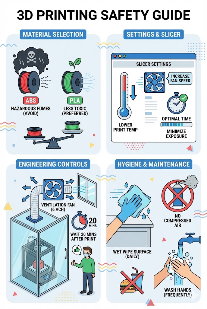
Rather than relying on forum hearsay, I took a rigorous approach. I utilized Notebook LM to synthesize data from 56 different scientific articles regarding emissions . The research highlights two invisible risk factors every maker should understand:
Ultrafine Particles (UFPs): Microscopic pieces of plastic and debris floating in the air .
Volatile Organic Compounds (VOCs): Gases released during the melting process, particularly from petroleum-based filaments like ABS and ASA .
Surprisingly, the research indicates that even PLA—often considered the “safe” option—can release VOCs equivalent to ABS depending on the brand, pigments, and additives used . In many cases, PLA is not just plant-based material; it has so many additives that it can cause risks .
To test the theory against reality, I set up a comprehensive sensor array using the Creality K2 Plus printing ASA . I placed air quality monitors inside the printer’s enclosure, directly outside near a HEPA filter, in the hallway, and downstairs .
The results were telling. The sensors demonstrated that a simple enclosure can act like a fireplace screen, keeping an estimated 95% of particles and gases contained . However, my testing also revealed a critical workflow error. In an attempt to clean the printer glass with alcohol, I inadvertently caused a massive spike in VOC readings, proving that sometimes our cleaning habits can be just as impactful as the printing itself .
Transparency: We may earn a commission when you make a purchase through our links. Minimal 3DP is a participant in the Amazon Services LLC Associates Program, an affiliate advertising program designed to provide a means for sites to earn advertising fees by advertising and linking to Amazon.com.
If you are reading this, you probably did exactly what I did last night: I wasn’t paying attention, saw a green update button, and just pressed it .
Normally, updates are a good thing. But in this case, I immediately regretted it. I was trying to record a video and needed my K2 Plus for its enclosed chamber, but the moment I installed the new firmware, I had nothing but errors and couldn’t print a single thing . Specifically, it wouldn’t even get to the preheating stage before crashing out with stepper timing errors .
Since I don’t use Creality Print, it took me a while to figure out how to manually roll back the firmware to a stable version . If you are stuck in the same boat, here is the step-by-step process to get your machine running again without using their slicer software.
Insert the USB drive into the port on the right-hand side of the machine .
Turn the printer back ON .
The screen will boot up and ask if you want to “Upgrade” to the version on the stick. Even though we are downgrading to an older version, hit Upgrade .
Note: The system might estimate this will take hours, but in my experience, it installs much faster than that . Just be aware that rolling back firmware will wipe any custom config files you had, so you will lose your customizations .
Transparency: We may earn a commission when you make a purchase through our links. Minimal 3DP is a participant in the Amazon Services LLC Associates Program, an affiliate advertising program designed to provide a means for sites to earn advertising fees by advertising and linking to Amazon.com.
In the domain of desktop manufacturing, we obsess over tangible costs. We calculate the price per kilogram of filament, analyze the depreciation of a nozzle, or measure the energy consumption of a heated bed. [cite_start]However, my research into optimization techniques highlights a critical variable often missing from the equation: Time[cite: 6].
[cite_start]For the past few years, Minimal 3DP has operated to bridge the gap between “Appliance Consumers” and “Engineering Enthusiasts”[cite: 2]. We’ve explored Klipper firmware, dissected OrcaSlicer profiles, and pushed prosumer hardware to its absolute limits. [cite_start]But as the market undergoes the “Great Bifurcation”—where machines diverge into locked-down appliances or complex open-source projects—the burden of configuration has shifted entirely to you, the user[cite: 2].
The current ecosystem often forces a binary choice: pay a premium for a “walled garden” ecosystem or spend hours scrolling through forums to find a configuration that doesn’t result in a layer shift.
In my strategic analysis of the channel, I identified a critical inefficiency. [cite_start]You aren’t coming to Minimal 3DP just for entertainment; you are coming for data[cite: 1]. You need the verified parameters that turn a chaotic build into a reliable tool. You need optimization without the trial-and-error cycle that kills throughput.
Today, I am launching the Minimal 3DP Patreon to solve this specific problem.
I do not view this platform as a “donation jar.” [cite_start]I view it as essential infrastructure—a “Hardware Bridge” designed to accelerate your workflow[cite: 3]. By joining, you are investing in a verified data utility that allows you to bypass the tinkering phase and get straight to production.
We are launching with the Operator Tier, designed specifically to let you buy back your time.
You want to print. By joining this tier, you get access to the Minimal 3DP Platform tools that streamline your workflow:
Export Settings as OrcaSlicer Profiles on OrcaSlicer Settings Recommender Stop guessing at parameters. Generate and export optimized profiles directly. https://go.minimal3dp.com/settings/
AI-based analysis on the Printer Reviews and Analysis Get deep, data-driven insights into hardware before you buy, leveraging our aggregated testing data. https://go.minimal3dp.com/reviews/
Ability to save invoices on the FDM Cost Calculator Move from hobbyist to professional by tracking project costs accurately and saving your history for client billing or internal records. https://go.minimal3dp.com/fdm-cost/
This launch marks a strategic pivot for Minimal 3DP. [cite_start]While I will always produce high-quality tutorials for YouTube, the Patreon allows me to serve as a Data Authority[cite: 1]. [cite_start]It funds the acquisition of new hardware for “Rooting” projects (like the upcoming K2 Plus deep dive) and supports the rigorous testing required to validate the tools I share[cite: 3].
If you are tired of “calibration hell” and want to treat your printer like the precision tool it is, I invite you to join us.
As many of you know, this past October got a little personal for me. I underwent heart surgery, and I’ve spent the last few months focused on recovery. I’m finally reaching the point where I feel like myself again—I even started physical therapy this week.
To commemorate this journey and mark getting back on my feet, I wanted to create a project that felt significant: a realistic, 3D-printed human heart.
Usually, a project like this would involve hunting down a specific STL or spending hours sculpting in Blender. Instead, I used this as an opportunity to test a new AI tool: Tripo 3.0.
Note: A big thank you to Tripo 3.0 for sponsoring this project. As always, while they are supporting the channel, the opinions and testing results below are entirely my own.
Tripo 3.0 is an AI generation tool capable of creating 3D models from simple text prompts or reference images. The developers claim it offers the “cleanest, sharpest, and most detailed geometry” in the AI 3D space.
That is a bold claim. We are used to AI models requiring hours of mesh repair before they are printable. However, after using it for this project, I have to admit—the topology was shockingly clean.
I started with a simple command: “Create a model of a realistic human heart.”
Result: It generated a highly detailed, anatomically correct heart. However, it was just the organ itself—no base, no stand. Great for anatomy, harder to display.
Next, I uploaded a reference image from Wikipedia and combined it with the text prompt.
Result: This was the winner. The AI not only generated the heart but interpreted the context of the image to include a display stand.
The Verdict: Both models generated in about two minutes. The level of surface detail—specifically the veins popping out from the surface—was stunning. For a “set it and forget it” tool, the quality was surprisingly high.
Getting AI models out of the browser and into the physical world is usually where the headache starts. Here is exactly how I handled the files for anyone looking to replicate this workflow.
Why? In my testing, the STL files exported at a very small scale, requiring manual resizing. The 3MF files imported into the slicer at a reasonable, printable size immediately.
I brought the model into OrcaSlicer. Even though the geometry was clean, organic shapes always need support help.
Scale: For the version without the stand, I scaled it to 150%. For a massive heart, I tested scaling up to 300% (though that would have taken forever to print).
Supports: I utilized Slim Tree Supports (Organic).
Adhesion: I added an Outer Brim to ensure the small contact points on the bottom didn’t detach.
Time: The stand version took roughly 1 hour 21 minutes. The larger, stand-less version took 4 hours 27 minutes.
Post-Processing: The supports snapped off cleanly. There was some minor scarring on the back of the stand-less model where it lay on the build plate (mostly due to my orientation choice, not the model geometry), but the display side was pristine.
While I used this for a personal commemorative piece, the toolset inside Tripo 3.0 is definitely aiming at the professional crowd.
Segmentation: I tested this on a robot model. The software automatically broke the single mesh into distinct parts (arms, legs, head), allowing you to edit or merge specific components.
Retopology: For those of you using Blender or ZBrush, the generated topology is workable, not the usual “soup of triangles” we see from photogrammetry or older AI tools.
I printed a realistic thyroid years ago for my wife after her surgery (she found it romantic, I promise), and this project felt like a similar closing of a chapter for me.
If you are looking to generate artistic models, figurines, or organic shapes without needing to master digital sculpting, this is the easiest workflow I have found to date.
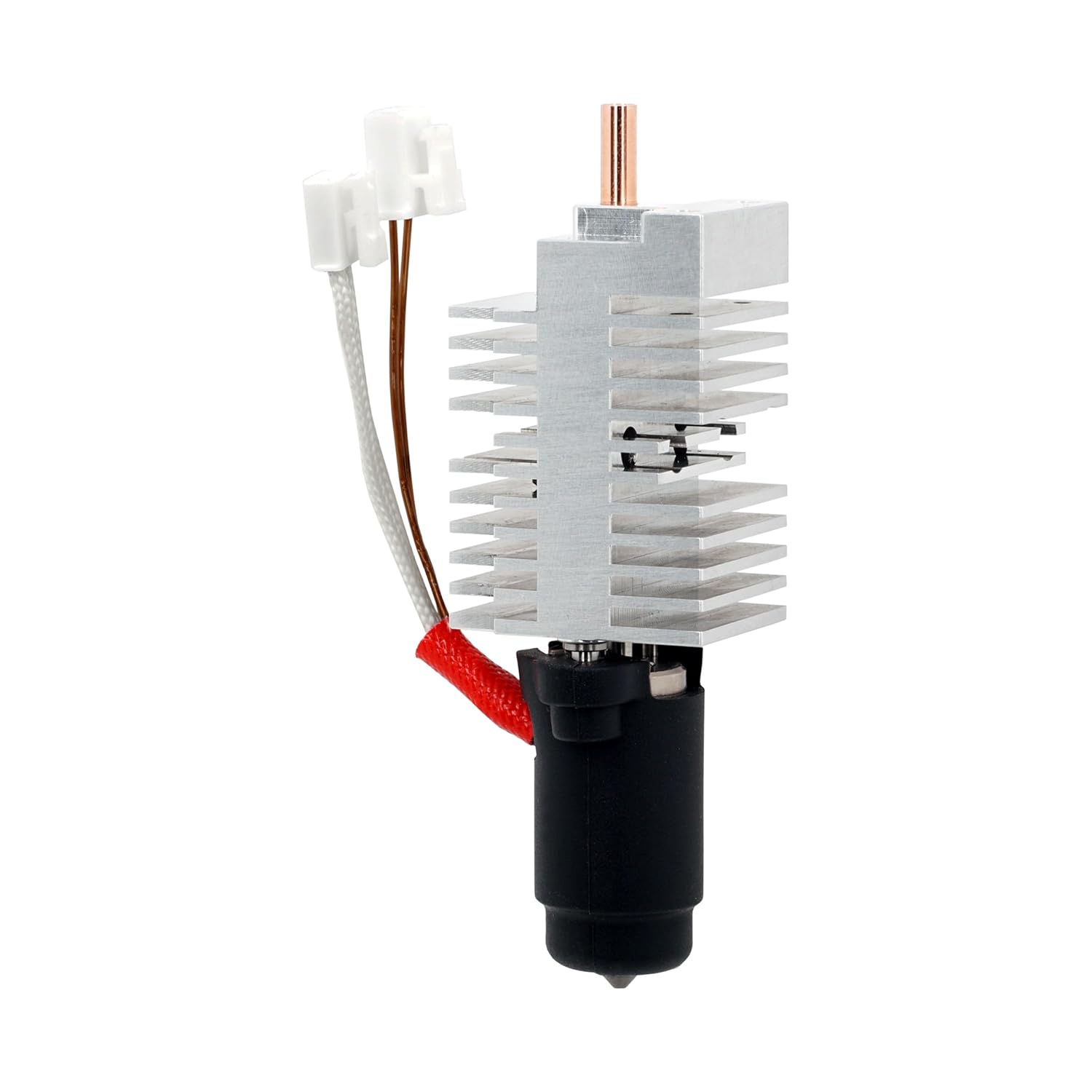
The Creality K2 Plus has established itself as a flagship machine, but for the “Engineering Enthusiast,” stock hardware is rarely the end of the road. In the latest installment of the K2 Plus Upgrade Series, I tackle a critical component swap: replacing the stock hotend with the Micro Swiss FlowTech system equipped with the CM2 High Flow Hardened Steel nozzle.
This guide covers the technical specifications, a direct weight comparison, and the step-by-step installation process to help you decide if this upgrade is right for your rig.
The primary motivation for this upgrade is flow performance and durability. While browsing upgrade paths, I secured the Micro Swiss FlowTech hotend, pairing it specifically with the CM2 High Flow nozzle.
It is important to distinguish between the nozzle options available for this ecosystem. Micro Swiss offers standard plated nozzles and generic high-flow versions, but the CM2 stands out because it utilizes hardened steel. This is a critical distinction for users printing with abrasive engineering materials like carbon fiber filled filaments.
Visually, the Micro Swiss unit features significantly larger and more complex cooling fins, suggesting improved thermal management. Interestingly, the heating element section appears slightly smaller on the FlowTech compared to stock.
In terms of mass—a critical factor for input shaping calibration—the difference is negligible:
Component
Weight
Stock Hotend
44 grams
Micro Swiss FlowTech
45 grams
This 1-gram difference confirms that the Micro Swiss is effectively a drop-in replacement that won’t drastically alter the toolhead’s mass characteristics. This means your existing input shaping profiles will remain largely valid.
The process begins by carefully unplugging the two connectors attached to the main breakout board. These connectors can be tight, so caution is required to avoid damaging the board headers.
Once disconnected, remove the two retaining screws located near the bottom plate of the hotend assembly.
Hardware installation is only half the battle. After powering on the machine, I verified that the thermistor was reporting ambient temperature correctly before attempting to heat the nozzle.
To validate the install, I printed a 3DBenchy using ASA filament.
Results:
✅ Extrusion quality: Excellent, consistent flow throughout
✅ Layer adhesion: Perfect interlayer bonding
⚠️ Bed adhesion: Lifting at the chimney (common with ASA on stock surface)
While the print suffered from a bed adhesion issue—a common struggle with ASA on stock build surfaces—the extrusion quality itself was excellent. The body of the Benchy looked “phenomenal,” confirming that the FlowTech is delivering consistent extrusion.
This project is sponsored by PCBWay. Whether you need custom PCB prototyping, CNC machining, or 3D printing services for your next build, PCBWay offers professional-grade manufacturing solutions.
The Micro Swiss FlowTech hotend paired with the CM2 High Flow nozzle represents a meaningful upgrade for K2 Plus owners who:
Print with abrasive engineering materials (carbon fiber, glass fiber, etc.)
Need higher flow rates for large prints
Want improved thermal management
Seek longer nozzle lifespan
The near-identical weight means minimal impact on your existing calibrations, while the hardened steel construction ensures durability for hundreds of hours of printing.
YouTube: Subscribe to Minimal 3DP on YouTube for more upgrade guides and technical deep dives.
Disclaimer: This post contains affiliate links. Minimal 3DP may earn a small commission at no extra cost to you, which helps fund future technical deep dives.
One of the biggest problems I have in my 3D printing journey is simply trying to remember which filament is best for which scenario. If I need a UV-resistant filament for an outdoor part, or if I need to know if a specific engineering-grade material is actually printable on my current setup, digging through PDF Technical Data Sheets (TDS) takes forever.
To solve this, I’ve developed a new app: the FDM Filament Recommendation Engine.
The goal of this application is to let you sort, query, and filter through over 40 different materials to find the one that fits your specific project needs.
I developed this by analyzing various manufacturer TDS records, but I know those aren’t always perfectly accurate. To validate the data, I also cross-referenced peer-reviewed journal articles. I utilized AI to help extract and organize this massive amount of data into a usable format.
I originally had three different choices for “strength,” but they were all telling me the same thing. I have simplified this to just General Strength and Compressive Strength to make the data easier to read.
You can filter by “Printability.” If you back the slider off to an 8, you’ll see familiar materials like PLA and PETG. If you look at engineering materials like PC or ASA, you’ll see that score drop significantly—reflecting the real-world difficulty of printing those materials.
This is probably the most useful feature. You can select multiple filaments (for example, UV-resistant materials like ASA, PC, and others) and hit “Compare.” This gives you a side-by-side look at their cost score, heat compatibility, and stiffness.
I’ve added information on whether a material can be annealed—the process of heating the print after printing to make the material stronger and more dimensionally stable.
I have added a feedback form to the site. If you have a better source of data than the TDS sheets or journal articles I have used, please feel free to submit it. My goal is to make this a complete repository of knowledge for us to use.
This project is sponsored by PCBWay. I want to thank them for their continued support of the Minimal 3DP channel.
If you are working on a project that requires custom PCBs, I highly recommend checking out their design services. They have powerful tools on their website to get an instant quote, and their help with PCB design layout starts at just $88.70 US.
I found a feature that is incredibly powerful for anyone running multiple build plates on a single printer: specifying bed types.
If you swap between a smooth PEI sheet, a textured plate, or a cool plate, you usually have to manually adjust your Z-offset or run a bed level every time. However, OrcaSlicer allows you to automate this process, saving your Z-offset and temperature settings based on the specific bed you select. For broader slicer tuning, visit the OrcaSlicer Tutorials Hub.
OrcaSlicer generally supports four standard bed definitions: Cool Plate, Engineering Plate, High Temp Plate, and Textured PEI Plate. Even if your specific brand of plate isn’t listed, you can use these presets as placeholders to trigger specific settings.
To enable this feature:
Open OrcaSlicer and go to Printer Settings.
Check the box for “Support multiple bed types”.
Once enabled, you will see a dropdown menu allowing you to select your active bed type directly in the main interface.
One immediate benefit of this feature is temperature management. Different bed materials require different surface temperatures.
For example, I typically use a smooth PEI high-temp plate at 60°C. However, I recently started using the BigTreeTech MENT BQ Cryo Grip ProGlacial beds. These are double-sided (smooth and textured), but they run best about 5 to 10 degrees cooler than standard PEI.
By utilizing the bed type settings in the Filament tab, I can assign specific temperatures to specific plate types (e.g., setting the “Cool Plate” slot to 55°C). This allows me to “set it and forget it”—the slicer handles the temp change automatically based on the bed I select.
The most powerful application of this feature is automating your Z-offset. To make this work, you need to pass the bed type variable from OrcaSlicer to your printer’s start code. After implementing this, refine extrusion consistency using Flow Calibration and ringing reduction with Input Shaping.
Once the printer receives the variable, you can use conditional logic (If/Else statements) in your printer’s configuration (like Klipper macros) to adjust the Z-offset.
Based on examples found on the Creality K2 Plus forums and AI-generated code, the logic works as follows:
Capture the Variable: The macro grabs the uppercase variable CURR_BED_TYPE.
If/Else Statements: The printer checks which bed is active and applies a specific offset.
Example: If using a glass plate, set Z-offset to 0.
Example: If using Textured PEI, set Z-offset to -0.03.
Fallback: You can include an else statement to handle any unknown bed types.
This feature adds a layer of convenience and optimization to your workflow. Whether you are looking to automate temperature changes for Cryo Grip plates or swap between smooth and textured sheets without releveling, specifying bed types in OrcaSlicer is a game changer.
Thanks for stopping by! I’m still recovering, so I appreciate your patience if this wasn’t up to my usual standards, but I look forward to talking to you again soon.
Have questions about your start G-code? Leave a comment on the video!
I’ve had a lot of time to think recently while recovering from heart surgery, and I put that time to use. Today, I want to talk about “the best 3D printer slicer settings” and what that really means.
We’ve all seen videos (even from my own channel) about the “best” settings. But when you open a modern slicer—my choice is OrcaSlicer—you’ll find hundreds, maybe thousands of different settings. The truth is, there is no single perfect setting for every scenario.
Rather than just giving you my opinion, I’m a big proponent of using Google Scholar. It’s a search engine for academic papers and journal articles. I typically filter my searches to find new articles (e.g., since 2021) to see what parameters affect what properties.
For example, a quick search for “FDM 3D printing process parameters” brings up articles that show exactly how slicer settings impact mechanical properties. I found one article I really like that provides a systematic survey of these parameters and their influence on part characteristics. It has a great diagram showing how settings affect:
Build time
Dimensional accuracy
Surface roughness
Flexural, compressive, and tensile strength
This research is incredibly helpful, but it’s not easy for everyone to parse. So, I started working on a program to help pull these settings from journal articles and give you a clear reference.
First, you select the filament you want to use. This is more than just a name—I’ve fed data from over 130 manufacturer technical data sheets into the app. I used AI to extract all the technical information (strength, heat distortion, glass transition temperature, chemical resistance, etc.) from those PDFs.
This means when you select a material like ABS, the app will give you:
Next, you set your print priority on a scale from 0 (I don’t care) to 100 (max priority) for four key areas:
💪 Strength: For functional parts, tools, and mechanical properties
⚡ Speed: Great for iterating on a design and rapid prototyping
✨ Quality: For display models, miniatures, and aesthetics
📏 Accuracy: Critical for prints that need to fit together
The app understands that these priorities often conflict. For example, maximum speed usually reduces quality. The tool balances these trade-offs based on your priorities.
What makes this tool different from other “best settings” guides:
✅ 130+ manufacturer technical data sheets analyzed
✅ Academic research from peer-reviewed journals
✅ Systematic approach to parameter optimization
✅ Material-specific recommendations based on properties
✅ Priority-based balancing of conflicting goals
None of this is “perfect,” but it’s designed to give you a clear idea of how to set your settings in your slicer based on actual research, not just my opinion.
I’m not saying this is the be-all, end-all, but if you’re new to 3D printing and trying to figure out what settings to use, this should be a great start for you.
I did add some affiliate links for different filaments on the side of the app. My hope is that this will help generate a little revenue that I can plow right back into my work for the channel and developing more free tools for the community.
🛒 Use affiliate links when buying filament (no extra cost to you)
Is the OrcaSlicer Expert Assistant really free?
Yes! The app is 100% free with no registration required. It runs entirely in your browser and doesn’t collect any personal data. I may add affiliate links to filament brands to help support development.
Will this work with other slicers like PrusaSlicer or Cura?
Yes! While it’s designed for OrcaSlicer, the principles and most settings translate directly to PrusaSlicer (OrcaSlicer’s parent), Cura, and other FDM slicers. The parameter names might be slightly different, but the concepts are universal.
How accurate are the recommendations?
The recommendations are based on peer-reviewed academic research and technical data from 130+ manufacturer data sheets. However, they’re starting points that should be refined through calibration for your specific printer, material batch, and environment. Think of it as an educated starting point rather than a final answer.
What if I have multiple priorities (e.g., both strength AND quality)?
That’s exactly what the priority sliders are for! Set each priority from 0-100, and the app will balance the recommendations. For example, if you set both strength and quality to 80, it will find settings that optimize both without sacrificing too much of either.
Which filaments are included in the database?
The app includes data for major filament types (PLA, PETG, ABS, ASA, Nylon, TPU, etc.) compiled from 130+ manufacturer technical data sheets. Check my complete filament guide for detailed comparisons.
Can I request new features or report bugs?
Absolutely! Please email me at minimal3dp@gmail.com or comment on the YouTube video. I’m actively developing this tool and appreciate all feedback from the community.
Choosing the right 3D printing filament can make or break your project. After years of testing dozens of brands and materials, I’ve compiled this comprehensive guide to help you find the perfect filament for any application.
PLA (Polylactic Acid) is the most popular 3D printing filament for good reason: it’s easy to print, doesn’t require a heated bed, and produces minimal odor. Perfect for beginners and decorative prints.
Best budget choice. SUNLU’s PLA offers exceptional value with excellent layer adhesion and dimensional accuracy. At under $14/kg, it’s my go-to for everyday printing.
Pros: Affordable, consistent diameter, great color selection Cons: Slightly more brittle than premium brands Best for: Prototypes, decorative prints, learning
Premium quality. OVERTURE is known for incredibly consistent diameter control (±0.03mm) and smooth finish. If you need reliability for important prints, this is worth the extra $6.
Pros: Consistent quality, smooth surface, minimal stringing Cons: Higher price point Best for: Final parts, gifts, detailed models
PLA+ offers significantly better layer adhesion and impact resistance compared to standard PLA, making it ideal for functional parts that need more durability.
The industry standard. eSUN’s PLA+ is the original and still one of the best. Prints like PLA but with 3-4x the impact strength. Perfect bridge between ease-of-use and functionality.
Pros: Excellent toughness, minimal warping, easy to print Cons: Slightly higher printing temperature Best for: Functional parts, tools, fixtures
Beautiful silk finish with metallic sheen. Perfect for decorative items, jewelry, and artistic prints. The copper and gold colors are especially stunning.
Tip: Print slowly (40-50mm/s) for best surface finish.
Natural wood fiber composite with authentic wood texture. Can be sanded and stained like real wood. Great for decorative items, models, and artistic projects.
Tip: Vary temperature (190-220°C) during print to create wood grain effect.
Carbon fiber reinforced PLA for enhanced rigidity. Excellent dimensional stability and a premium matte finish. Warning: Use hardened steel nozzle to prevent wear.
Best for: Drone parts, RC car components, rigid structures
Best all-around PETG. OVERTURE’s PETG offers excellent layer adhesion, minimal warping, and good chemical resistance. Perfect for mechanical parts, containers, and outdoor items.
Print Settings: 235-245°C hotend, 70-80°C bed Pros: Strong, flexible, chemical resistant Cons: Can be stringy (use retraction tuning) Best for: Mechanical parts, containers, outdoor items
Premium ABS with minimal warping. Polymaker’s formula is easier to print than standard ABS and produces less odor. Excellent for automotive parts and functional components.
Best for outdoor use. ASA has excellent UV resistance (won’t fade or degrade in sunlight) while maintaining ABS’s strength and heat resistance. Perfect for outdoor fixtures, signs, and garden items.
Why ASA > ABS for outdoors: Won’t yellow or become brittle from UV exposure Best for: Outdoor fixtures, automotive trim, signage
Best TPU for beginners. 95A hardness offers good balance between flexibility and printability. Works on most direct drive printers without modifications.
Strong and flexible nylon for mechanical parts. Excellent wear resistance and low friction coefficient make it perfect for gears, bushings, and living hinges.
Print Settings: 250-270°C hotend, 70-80°C bed, must keep dry Best for: Gears, bushings, mechanical parts, living hinges
Heat-stabilized PLA+ with enhanced temperature resistance. Can withstand temps up to 90°C after annealing. Prints like PLA but performs like engineering plastic.
Process: Print normally, then anneal at 100°C for 1 hour in oven Best for: Functional parts, automotive, under-hood applications
Virtually unbreakable. PC is used for bulletproof glass and riot shields. Excellent for protective cases, safety equipment, and impact-resistant parts.
Efficient filament dryer with adjustable temperature. Essential for hygroscopic materials like Nylon, PETG, and PVA. Prevents moisture-related print issues.
Q: What’s the best filament for beginners?
A: Standard PLA. It’s affordable, easy to print, and doesn’t require a heated bed. Start with SUNLU PLA ($13.99) for best value.
Q: Can I print PETG without an enclosure?
A: Yes! PETG prints well without enclosure, unlike ABS/ASA. Just use 70-80°C bed temp and minimal cooling.
Q: Do I need a special nozzle for carbon fiber filaments?
A: Yes, hardened steel nozzle is essential. Brass will wear out quickly from abrasive CF particles.
Q: How long does filament last in storage?
A: PLA/PLA+: 1-2 years if kept dry. PETG/Nylon: 6-12 months. Always use desiccant in storage.
Q: Why is my nylon print brittle?
A: Most likely moisture absorption. Dry your nylon for 8-12 hours at 70-80°C before printing.
Q: Can I mix brands/materials?
A: Yes for same material type (different PLA brands work fine together). No for different materials in same print without proper interface settings.
Choosing the right filament depends on your specific application:
Just starting out? SUNLU PLA ($13.99)
Need strength? eSUN PLA+ ($20.99)
Functional parts? OVERTURE PETG ($21.99)
Outdoor use? Polymaker ASA ($29.99)
Flexible parts? OVERTURE TPU ($23.99)
Engineering? Nylon or Nylon CF
Remember: The “best” filament is the one that meets your specific needs at the right price point. Don’t overspend on engineering materials for decorative prints, but don’t compromise on quality for functional parts.
Have questions about which filament is right for your project? Drop a comment below and I’ll help you choose!
This post contains affiliate links. As an Amazon Associate, I earn from qualifying purchases at no cost to you. All recommendations are based on personal testing and experience.
If you’ve ever thought about selling your 3D prints, one of the first and biggest hurdles is figuring out how to price them accurately. Most people just look at the material and electricity costs, but that’s a quick way to lose money.
I recently read an article called “Refined Cost Calculation Framework for FDM Parts,” which breaks down the entire cost process into much greater detail. It factors in everything:
Machine costs and energy
Tooling costs (like nozzle wear and build sheet lifespan)
Material and model costs
Labor costs (for setup, slicing, and post-processing)
This model is far more accurate, but the one major problem is that with so many inputs, it’s incredibly hard to keep it all straight.
I started building a spreadsheet to manage this for myself, and… well, it turned into a full-blown web tool.
I’ve created a 3D Print Cost Calculator that’s now live on my website. You can find it under the “M3DP Tools” menu item.
This tool is designed to help you capture all those hidden costs and generate a detailed quote, which you can save for your own records or print as a PDF to send to a customer.
In it, you can dial in specific parameters for:
Labor: Set your own hourly rate for slicing, machine setup, and post-processing.
Machine: Input your machine’s cost and estimated lifespan in hours.
Components: Add costs and lifespans for your nozzle and build plate (I found research suggesting a PEI sheet can last 5,000+ hours!).
Failure Rate: Add a percentage to help cover the cost of failed prints.
Markup: Add a final markup to the total calculated value.
One of the most important features: everything is saved 100% client-side. It all stays on your machine; nothing is saved to my server. You can even save and load different setting profiles.
I put together a video walking through the entire calculator, using a real-world part as an example. I show you where to find the tool, how to pull the data from your slicer, and how to fill out every field.
This tool is brand new, and I’m still testing it and adding features.
Please check it out, give it a try, and let me know what you think. If you see any errors, have suggestions for new features, or think of any costs that I’m not currently capturing, please let me know in the video comments or contact me through the site.
Hopefully, this helps you price your prints more accurately and professionally. I look forward to hearing what you think!
If you’re like me, you’re constantly on the lookout for the latest and greatest features to elevate your 3D prints from good to flawless.1 This relentless pursuit of perfection is the lifeblood of the 3D printing community, and it’s a spirit embodied by the team behind OrcaSlicer. More than just a piece of software, OrcaSlicer has established itself as a dynamic, open-source project at the vanguard of Fused Deposition Modeling (FDM) technology.2 It’s a slicer built by and for the community, characterized by a rapid development cycle that consistently delivers powerful, cutting-edge tools into our hands.
It is in this spirit of continuous innovation that the developers have released OrcaSlicer version 2.3.1 Alpha.1 This isn’t just a minor update; it’s a significant leap forward, offering an exciting glimpse into the future of slicing. This release is packed with enhancements that promise to refine our workflows and improve our print quality in tangible ways.
A Glimpse of the Future: What’s New in Version 2.3.1 Alpha?
The 2.3.1 Alpha release is a treasure trove of new functionalities that address various aspects of the printing process. While this guide will focus on one revolutionary feature, it’s worth taking a moment to appreciate the breadth of improvements included in this update.1 The key additions are:
A new sparse infill rotation system for stronger, more efficient internal structures.
Substantial changes and improvements to the fuzzy skin feature, offering more creative control over surface textures.
Integrated input shaping calibration for printers running Klipper firmware.
A new junction deviation calibration test for users with Marlin-based machines.
And, the focus of our deep dive today, a completely redesigned and more intuitive method for flow rate calibration.1
Each of these features deserves its own detailed exploration, and I plan to cover them in future articles and videos. However, the new flow calibration method represents such a fundamental shift in approach and offers such a significant improvement in accuracy and ease of use that it warrants a dedicated, comprehensive guide. My goal here is to provide a focused, exhaustive walkthrough that will empower you to master this new tool immediately, without wasting your time.1
For those who prefer a visual demonstration, I have created a complete video walkthrough that complements this written guide. You can watch it to see the entire process in action, from launching the test in OrcaSlicer to analyzing the physical prints.
Before we dive into the technical details, it’s important to understand the context of an “Alpha” release. In the world of open-source software, an alpha version is far more than just an early, potentially unstable preview. It represents a philosophical choice that lies at the heart of community-driven development.2 Unlike the closed, internal testing of proprietary software, a public alpha is a transparent invitation for the most engaged users to become active participants in the development process.
The OrcaSlicer project thrives on this collaborative model, offering not just stable releases but also “Nightly Builds” for those who want to test the absolute latest code.2 When you download and use OrcaSlicer 2.3.1 Alpha, you are not merely a consumer; you are a collaborator. The feedback you provide, particularly through well-documented bug reports, is invaluable data that helps the developers refine, debug, and perfect these new features before they are rolled into a stable release.1 This guide will not only show you how to use the new flow calibration but also how to responsibly contribute back to the project that provides these powerful tools for free.
From Subjective Feel to Objective Data: A Paradigm Shift in Flow Calibration
To fully appreciate the brilliance of the new flow calibration method, we must first understand the limitations of the one it replaces. For a long time, flow rate calibration in OrcaSlicer (and many other slicers) involved printing a series of square patches, each with a different flow modifier.[4, 5] The top surface of these squares was printed with a simple diagonal line pattern, moving back and forth at a 45-degree angle.1
The process for determining the correct flow rate was almost entirely subjective. The official instruction was to run your fingers across the printed squares and select the one that felt the smoothest to the touch.1 While this method can work, its effectiveness is heavily dependent on the user’s experience and tactile sensitivity. A beginner might struggle to discern the subtle differences between patches, while even an expert’s judgment could be influenced by lighting or the specific texture of the filament. This subjectivity was the primary weakness of the old system, creating a barrier to achieving consistent, repeatable results.
Introducing the Archimedean Chord: A Smarter Pattern for a Smarter Slicer
The 2.3.1 Alpha release replaces the ambiguous diagonal pattern with a far more intelligent design: a concentric pattern based on an Archimedean chord.1 This isn’t just a cosmetic change; it’s a fundamental re-engineering of the test based on geometric principles.
An Archimedean spiral is a shape defined by a path that moves away from a central point at a constant angular velocity. In simpler terms, the distance between each successive turn of the spiral remains constant. When the toolhead of a 3D printer traces this path, it should lay down a series of perfectly concentric lines with a uniform gap between them. This geometric purity is the key to the test’s effectiveness. Any deviation from the ideal amount of extruded filament—either too much or too little—will immediately disrupt this perfect, repeating pattern in a way that is visually and tactically obvious.
Unlike the old diagonal pattern, where over-extrusion might simply result in a slightly rougher surface, the Archimedean pattern provides clear, unmistakable evidence. This new test, as highlighted in the updated OrcaSlicer wiki, is now the recommended method for dialing in your flow rate.1
This evolution from a tactile, experience-based method to a visually explicit one represents more than just a technical upgrade; it’s a move that democratizes precision in 3D printing. It effectively lowers the barrier to entry for achieving one of the most critical calibrations, empowering users of all skill levels to diagnose and resolve extrusion issues with a newfound level of confidence.
The old method relied on an acquired skill—a developed “feel” for surface smoothness that created a knowledge gap between newcomers and seasoned veterans.1 The new test replaces this subjectivity with objective, observable data. Over-extrusion presents itself as distinct ridges where “the edge of the circle is really sticking out,” while under-extrusion creates clear “valleys” or gaps between the lines.1 These are not matters of opinion; they are measurable physical artifacts.
This aligns perfectly with OrcaSlicer’s overarching mission: to package “advanced calibration tools” within a “user-friendly interface” that supports a “wide printer compatibility”.2 By making a foundational calibration process like flow rate easier to perform and more reliable to interpret, the software empowers a much broader range of users to achieve superior print quality. It removes the gatekeeper of subjective “feel” and replaces it with the clarity of visual evidence. This new feature is a perfect encapsulation of the project’s philosophy: it doesn’t just add power for experts; it engineers that power in a way that elevates the entire community.
A Practical Guide: Dialing in Your Flow Rate with the New Test
Before you jump into printing the new calibration test, a little preparation will ensure you get the most accurate results possible.
First, this test is designed to refine an existing flow rate, not to establish one from absolute zero. It is most effective when you start with a filament profile that is already reasonably well-configured. The calibration test works by applying small positive and negative modifiers to your filament’s current flow ratio setting. As the transcript notes, “it doesn’t reset it back to one. It’s based on what it’s currently set at”.1 So, if your filament profile’s flow ratio is already set to 0.98, the test chips will be modifiers based on that value.
Second, for the most scientifically accurate calibration, it’s crucial to follow the recommended order of operations. According to the official OrcaSlicer wiki, you should always calibrate temperature before calibrating flow rate.4 The temperature of your nozzle directly affects the viscosity of the filament, which in turn impacts how it flows. Dialing in your temperature first ensures that you are calibrating flow under the correct thermal conditions.
With your slicer open and your printer profile selected, launching the new test is straightforward.
Navigate to the top menu bar.
Click on the “Calibration” dropdown.
Select “Flow Rate.” A new test plate will be automatically generated in your workspace.
You will see a series of small, square chips laid out on the build plate. Each chip is labeled with a modifier value, such as 0, -0.01, +0.01, etc. This is the new, recommended test that utilizes the Archimedean pattern.1
Once the test plate is generated, simply slice it using the filament profile you wish to calibrate and send it to your printer. While it’s printing, prepare a well-lit area for inspection. Good lighting is critical for visually identifying the subtle surface differences between the test chips.
Step 3: Interpreting the Print – The Art of Sight and Touch
This is the most critical part of the process. Once the print is finished and has cooled, carefully remove it from the build plate. You will now analyze each chip, using both your eyes and your fingertips, to find the one that represents the “Goldilocks” zone of perfect extrusion.
Over-extrusion occurs when the printer pushes out too much filament. On the Archimedean pattern, this is incredibly easy to spot.
Visual Cues: Look for concentric circles where the edges are raised and pronounced. As the transcript describes, “the edge of the circle is really sticking out”.1 This happens because the excess plastic has nowhere to go and is forced upwards, creating distinct ridges. The surface may look overly glossy and lose fine detail.
Tactile Cues: When you run your finger across an over-extruded chip, it will feel bumpy and rough. You will be able to clearly feel the ridges formed by the excess filament. The chips with positive modifiers (e.g., +0.03, +0.05) are most likely to exhibit these characteristics.
Under-extrusion is the opposite problem: the printer is not pushing out enough filament to fill the toolpath completely.
Visual Cues: Look for visible gaps between the concentric lines. You may be able to see the layer below through these gaps. The transcript refers to these as “valleys” in the surface.1 The surface might also have a dull, matte, or unfinished appearance because the lines are not properly squishing together.
Tactile Cues: An under-extruded chip will feel textured or even hollow. Your finger will catch on the gaps between the lines, giving it a rough or scratchy feel. The chips with negative modifiers (e.g., -0.03, -0.05) are the primary candidates for this issue.
The “Goldilocks” Zone – Identifying the Optimal Result
Your goal is to find the single chip that is perfectly smooth, both visually and by feel.1
The Ideal Chip: The best chip will have a uniform, smooth top surface with a consistent, healthy shine.1 The concentric lines should be laid down perfectly next to each other with very little to no visible gaps. When you run your finger across it, it should feel almost like a single, solid surface. In my own testing for the video, the chip labeled 0 was the best, indicating my existing flow rate was already well-calibrated.1
An Important Nuance: It is crucial to understand one key detail from the official documentation: “it is okay to have a visible line between the inner and outer spiral”.1 The goal is not to create a completely fused, monolithic surface where the lines are indistinguishable. The perfect result is one that shows distinct lines laid down with “very little gap between” them.1 Do not mistake the faint line between toolpaths for under-extrusion. You are looking for the smoothest possible surface that is free of ridges (over-extrusion) and significant valleys (under-extrusion).
Step 4: Applying the Results and Updating Your Profile
Once you have identified the best chip, updating your filament profile is incredibly simple. The value printed on the chip is the exact modifier you need to apply to your current flow ratio.
The logic is simple addition or subtraction:
If you picked a chip with a positive value (e.g., +0.02), you add that value to your current flow ratio.
If you picked a chip with a negative value (e.g., -0.03), you subtract that value from your current flow ratio.
If you picked the 0 chip, no changes are needed.
Let’s use the concrete example from the transcript: imagine your filament’s flow ratio was set to 0.98 and you determined that the chip labeled +0.01 was the smoothest. Your new flow ratio would be $0.98 + 0.01 = 0.99$.1 This direct arithmetic is a significant improvement in user experience over older, more complex percentage-based formulas.[4, 5]
To make the change in OrcaSlicer:
Go to the “Filament” tab in the left-hand panel.
Click the “Edit preset” icon next to your chosen filament profile.
In the filament settings window, scroll down until you find the “Flow Ratio” parameter.
Enter your newly calculated value.
Crucially, click the “Save” icon at the top of the window to save your changes to the profile. Forgetting this last step is a common mistake that will cause you to lose your newly calibrated value.
The Enabler’s Guide: Responsible Use of Alpha Software
Choosing to use alpha software is choosing to step onto the front lines of development. It’s a decision that reframes your role from a passive user to an active tester and contributor. Every print you run, every setting you tweak, provides real-world data that is impossible to replicate in a controlled lab environment. By engaging with these new features early, you are providing an invaluable service to the developers and the entire OrcaSlicer community. You are helping to forge the tools that everyone will be using in the next stable release.
How to Submit an Effective Bug Report: A Checklist
Finding a bug in alpha software is not a failure; it’s a success. It’s an opportunity to contribute directly to the project’s improvement. However, the usefulness of your discovery depends entirely on the quality of your bug report. A vague or incomplete report is often unusable. To help you make the most impactful contributions, here is a checklist for submitting an effective bug report on the OrcaSlicer GitHub page, based directly on best practices.1
Step
Action
Why It’s Important
1
Search First
Go to the OrcaSlicer GitHub “Issues” page and search to see if your bug has already been reported.
2
Provide Context
State the exact OrcaSlicer version (e.g., 2.3.1 Alpha), your Operating System (e.g., Windows 11, macOS Sonoma), and OS version.
3
Document Steps
Write a clear, numbered list of the exact steps required to reproduce the error. Be as specific as possible.
4
Include Your Setup
Mention the specific 3D printer profile you are using (e.g., Voron 2.4, Bambu Lab X1C, Creality Ender 3).
5
Add Visuals & Logs
Attach screenshots that clearly show the issue. If the slicer crashes, include the debug log file it generates.
A well-structured bug report is one of the most powerful contributions a user can make to an open-source project. It transforms a moment of frustration into a constructive step toward a more robust and reliable piece of software for everyone. Despite its “Alpha” status, my own experience with version 2.3.1 has been that it “seems rock solid,” a testament to the quality of the developers’ work and likely the result of excellent community feedback during the nightly build phase.1
The introduction of the Archimedean chord flow calibration in OrcaSlicer 2.3.1 Alpha is a definitive step forward for precision 3D printing. By replacing a subjective, tactile test with a visually objective and geometrically intelligent one, OrcaSlicer has made a critical calibration process more accessible, repeatable, and accurate for users of all experience levels. It is a smarter test for a smarter slicer, and a perfect example of the thoughtful innovation that defines the project.
Your experience and feedback are what make the 3D printing community thrive. Now that you’ve learned about this new feature, I encourage you to join the conversation.
Have you tried the new flow test? What were your results? Is there another new feature in the 2.3.1 Alpha release that you feel I should highlight in a future guide? As I always say, “just leave me a comment and I’ll get back to you as soon as I can”.1
If you found this guide valuable, please consider giving it a few ‘claps’ here on Medium. This is a simple, free way to show your support, and it helps the platform’s algorithm show this article to more people who might benefit from it.
For more deep dives, tutorials, and the latest updates in 3D printing and OrcaSlicer, be sure to subscribe to my YouTube channel and follow me here on Medium.1
The OrcaSlicer Ecosystem: References and Further Reading
To continue your journey and become more involved with the OrcaSlicer project, here are the essential official resources. I strongly recommend bookmarking these to ensure you are always getting information from the primary source.
Official OrcaSlicer GitHub Repository: This is the home of the project. Here you can download the latest stable and alpha releases, read the full release notes, and report bugs.2
Official OrcaSlicer Wiki: An invaluable resource for detailed documentation on all of OrcaSlicer’s features, including the main Calibration page which provides a broader overview of the entire tuning process.4
Official OrcaSlicer Discord Server: The best place to engage with the community in real-time, ask questions, and get support from fellow users and the developers themselves.2
Finally, I want to extend a heartfelt thank you to all of my subscribers and members. Your support is what makes it possible for me to create in-depth content like this guide. Thank you for being a part of this community.1
Hey everyone! In my latest video, I dove deep into a 3D printing setting that often gets overlooked but makes a massive difference in your final prints: line width. For a long time, I was all about chasing faster print times, but I’ve come to realize that optimizing for quality and strength is well worth a few extra minutes – and line width is a key player in achieving just that [00:35].
What I Learned (and You Should Too!):
One of the biggest takeaways for me was just how much line width impacts the strength of your parts. Think about it: wider lines mean more material is laid down and there’s greater overlap between those lines, especially when it comes to printing walls. This significantly reduces those annoying little voids and makes your prints much more structurally sound [01:25], [03:06].
In the video, I specifically explored the line width settings within Orca Slicer. It’s pretty cool how much control you have, with options for the default width, the first layer, outer walls, and even the top surface [01:38].
Through my research (and a bit of trial and error!), I found that for a standard 0.4mm nozzle, bumping up the default line width to around 0.5mm (that’s 125%) seems to be a sweet spot. This aligns with recommendations in the Orca Slicer wiki and what others in the community are finding [05:10].
The best part? I was genuinely surprised at how little impact these adjustments had on the overall print time. The test print I showed in the video only took about 7 seconds longer with the optimized settings [10:06]. That’s a tiny trade-off for a noticeable improvement in quality!
Speaking of quality, I was really happy with how much cleaner the top surface looked after making these changes. You could see a real difference in how those layers blended together, resulting in fewer visible lines [11:22].
Oh, and here’s a little bonus tip I shared in the video: if you’re struggling with removing support material, try using a slightly thinner line width (smaller than your nozzle diameter) for your support structures. It makes them much easier to break away [08:37].
Give it a Shot!
Ultimately, what I wanted to show in this video is that taking the time to dial in your line width settings is well worth the effort. It’s all about finding that balance between print speed, the quality of your finished product, and the overall strength of your 3D prints [12:33].
Check out the full video for a more in-depth look and to see the results for yourself!
Let me know in the comments what line width settings you’ve found work best for you – I’m always learning! What else are you curious about in the world of 3D printing?
3D printing involves a lot of intricate settings to achieve the best possible results. One of the advanced features in Orcaslicer that can significantly impact print quality is extrusion rate smoothing. This post will explore what it is, why it’s important, and how to use it effectively.
Extrusion rate smoothing, similar to Prusaslicer’spressure equalizer, is a feature that limits the rate of extrusion volume change below a certain threshold. In simpler terms, it helps Orcaslicer manage how much plastic needs to be pushed out by the extruder. Think of it as gently applying the brakes in a car rather than jamming them on. It smooths out the start and stop of extrusion, especially during speed changes at corners and bridges.
During printing, the printer constantly speeds up and slows down, especially at corners and overhangs. These speed changes necessitate changes in the amount of plastic being pushed out. Sudden changes can be difficult for the extruder and firmware to handle, leading to artifacts like bumps and bulges. Extrusion rate smoothing creates speed ramps, gently slowing down before a change and gradually speeding up afterward. This makes it easier for the extruder to keep up, reducing unwanted artifacts.
Extrusion Rate Smoothing, Pressure Advance, and the Motion Planner
The printer’s firmware has a motion planner that interprets speed change commands and translates them into motor movements. Pressure advance calculates the necessary slowdown to reach the target speed. Extrusion rate smoothing regulates the pressure changes, creating a smooth ramp-up and ramp-down of pressure. Without it, sudden speed changes can cause blobs and artifacts.
In OrcaSlicer, the extrusion rate smoothing settings can be found in the speed section of the process parameters. These settings include segment length and an option to apply it only to external features.
A lower ERS value means more aggressive smoothing, and a higher value means less smoothing.
If the ERS value exceeds the maximum, it won’t be applied.
Extrusion rate smoothing is most useful for high accelerations and large flow rates, such as on a Voron with a high flow hotend and when pressure advance is set.
For Bowden printers, especially with flexible filaments, a lower ERS value is generally better. Direct drive printers can typically use higher values.
This value may need to be adjusted when changing acceleration or if you notice inconsistencies.
It’s a user-determined value, so experimentation is key.
Potential downsides include increased print time (though this is rare) and a possible loss of fine detail in some cases.
Crucially, extrusion rate smoothing won’t solve problems caused by an improperly calibrated printer.
The ERS value sets the maximum rate of change for extruded plastic, not the extrusion speed itself.
Start with recommended values (60-80% of the maximum) and increment by 10%.
Use low rates for Bowden setups with flexible filaments and higher rates for direct drive.
Pay close attention to overhangs to assess the effect of the setting.
Don’t exceed the maximum ERS value.
If using Klipper, calibrate pressure advance before adjusting extrusion rate smoothing.
Extrusion rate smoothing is a powerful tool in OrcaSlicer for optimizing print quality. By understanding its mechanics and how to adjust the settings, you can achieve smoother, more consistent 3D prints.
Have you ever wondered how fast your 3D printer can truly go? When I get a new printer or see a new model released, the first question that pops into my head is always, “How fast can I print with this thing?”
This post will explore how to determine the optimal print speed for your 3D printer, ensuring both speed and quality.
Infill: While not a major time-saver, adjusting infill patterns and density can slightly reduce print time.
Wall Thickness: Reducing the number of walls can significantly decrease print time, but it can also compromise the model’s strength.
Layer Height: Increasing layer height generally speeds up printing, but it can also affect print quality and part strength.
Other Parameters: Factors like print speed, infill density, and layer height also impact the mechanical properties of the printed part, according to research. Finding the balance between speed and strength is crucial.
Max Flow Rate: Each extruder has a maximum flow rate, which determines how much filament it can push out per second. Exceeding this limit leads to inconsistent extrusion, poor print quality, and weaker parts.
Ellis’s Print Tuning Guide provides valuable information and equations to calculate your extruder’s max flow rate. A simple test involves extruding a known length of filament at increasing speeds until you observe a noticeable drop in extrusion quality.
One of the key points that Ellis’ guide points out is that using approximate values (Table 1) is possible.
Determine Max Flow Rate: Conduct tests as described above to find your extruder’s maximum volumetric flow rate.
Set Volumetric Speed: Adjust the volumetric speed setting in your slicer software to match your calculated max flow rate.
Optimize Print Profiles: Experiment with different print speed settings for various parts of the model, ensuring that the speeds for visible features do not exceed the calculated safe limit.
Test and Iterate: Print test parts and adjust parameters based on the results. Observe print quality, part strength, and overall print time.
Model Size: Smaller models may not allow the printer to reach maximum speed due to acceleration and deceleration times.
Part Complexity: Complex models with intricate details may require slower print speeds to ensure accurate and high-quality results.
By carefully considering these factors and conducting thorough testing, you can optimize your 3D printer’s print speed while maintaining excellent print quality and part strength.
Disclaimer: This information is for general guidance only. Always refer to your printer’s manual and manufacturer’s recommendations for specific instructions and safety guidelines.
I hope this guide helps you unlock your 3D printer’s full potential!
With my previous website, I put it together with Wordpress. As what typically happens, WordPress was just too cumbersome for me to maintain. Additionally, it seemed like someone was always trying to hack it. It was a pain and I worried about the hacks.
I have used Hugo in the past and I thought I would try to rewrite the site in it. I liked the Docsy theme but I was not sure I could create the Klipper Calibration website. It turns out it was easier that I thought.
One of my main goals for creating this site, is the Klipper Calibration calculators I have put together. I have my Klipper Calibration Spreadsheet but many people are requesting edit access. To simplify things, I thought it would be a good idea to create these online tools. It also gave me the opportunity to do some simple programming. It has been a while.
Because I am using Docsy, there are tools built in to leave comments and post issues on github. I thought this integration would be helpful as I tried to improve and expand the tools. I am looking forward to the feedback. I know that there is room for improvement.
To many time I do not document my work well enough. I have several different tools for reference and documentation. Because it is several different tools, I never know where to look. With this in mind, I am hoping this site can serve as a repository of knowledge for my work. I sometime wish I had more time. There are so many cool ideas to try. Hopefully, I will have a chance to explore.
The blog is a minor feature for me. I always have good intentions for keeping it up but I always have trouble finding the time. We will see how this iteration goes. I am thinking that Hugo will make it easy. A lot of content here was done via my iPhone. Working Copy and Textastic are amazing apps and worth every penny.
According to Prusa3D, Max Volumetric Speed is defined as:
The Maximum volumetric speed setting (MVS) is one of the most powerful features in PrusaSlicer. The MVS setting essentially creates a manager for the maximum amount of filament that the slicer will attempt to push through your 3D printer’s hotend.
Dial in Your Prints: OrcaSlicer Max Flow Rate Calibration Test
Stop printing with gaps and blobs! Master your flow rate with OrcaSlicer’s built-in Max Flow Rate Calibration Test.
This beginner-friendly tutorial will guide you step-by-step through the entire calibration process. Learn how to:
Access and configure the Max Flow Rate test in Orca Slicer
Print the test model and identify the optimal flow rate for your filament
Apply the new flow rate settings to achieve flawless prints with consistent material extrusion
Say goodbye to under-extrusion and hello to smooth surfaces and sharp details! This video is perfect for anyone who wants to take their 3D printing to the next level with OrcaSlicer.