Welcome to the Minimal 3DP blog! I publish in-depth tutorials, honest product reviews, and maker news every week. All content is based on real hands-on experience.
📺 Watch This Tutorial on YouTube
Prefer videos? Subscribe for long-form tutorials, slicer deep-dives, and tested build guides.
New content published weekly! Subscribe on YouTube to get notified of new tutorials.
M3DP News
New Minimal 3DP Website
This is the new Minimal 3DP website. I have worked to create a Klipper calibration and calculator that the community could use. Hopefully, you find it useful.
Minimal 3DP YouTube Banner
Photo: Mike Wilson / CC-BY-CA
New Website
With my previous website, I put it together with Wordpress. As what typically happens, WordPress was just too cumbersome for me to maintain. Additionally, it seemed like someone was always trying to hack it. It was a pain and I worried about the hacks.
I have used Hugo in the past and I thought I would try to rewrite the site in it. I liked the Docsy theme but I was not sure I could create the Klipper Calibration website. It turns out it was easier that I thought.
Klipper Calibration
One of my main goals for creating this site, is the Klipper Calibration calculators I have put together. I have my Klipper Calibration Spreadsheet but many people are requesting edit access. To simplify things, I thought it would be a good idea to create these online tools. It also gave me the opportunity to do some simple programming. It has been a while.
Because I am using Docsy, there are tools built in to leave comments and post issues on github. I thought this integration would be helpful as I tried to improve and expand the tools. I am looking forward to the feedback. I know that there is room for improvement.
Projects
To many time I do not document my work well enough. I have several different tools for reference and documentation. Because it is several different tools, I never know where to look. With this in mind, I am hoping this site can serve as a repository of knowledge for my work. I sometime wish I had more time. There are so many cool ideas to try. Hopefully, I will have a chance to explore.
Blog
The blog is a minor feature for me. I always have good intentions for keeping it up but I always have trouble finding the time. We will see how this iteration goes. I am thinking that Hugo will make it easy. A lot of content here was done via my iPhone. Working Copy and Textastic are amazing apps and worth every penny.
Posts
Creality K2 Plus Upgrade Series: Installing the Micro Swiss FlowTech Hotend
Complete technical guide to upgrading your Creality K2 Plus with the Micro Swiss FlowTech hotend and CM2 High Flow hardened steel nozzle. Includes weight comparison, installation steps, and calibration tips.
By Mike Wilson |
The Creality K2 Plus has established itself as a flagship machine, but for the “Engineering Enthusiast,” stock hardware is rarely the end of the road. In the latest installment of the K2 Plus Upgrade Series, I tackle a critical component swap: replacing the stock hotend with the Micro Swiss FlowTech system equipped with the CM2 High Flow Hardened Steel nozzle.
This guide covers the technical specifications, a direct weight comparison, and the step-by-step installation process to help you decide if this upgrade is right for your rig.
The Hardware: FlowTech & CM2 Nozzle
The primary motivation for this upgrade is flow performance and durability. While browsing upgrade paths, I secured the Micro Swiss FlowTech hotend, pairing it specifically with the CM2 High Flow nozzle.
It is important to distinguish between the nozzle options available for this ecosystem. Micro Swiss offers standard plated nozzles and generic high-flow versions, but the CM2 stands out because it utilizes hardened steel. This is a critical distinction for users printing with abrasive engineering materials like carbon fiber filled filaments.
Key Specifications
The CM2 boasts a flow rate of 50 cubic millimeters per second, ensuring the hotend can keep up with the rapid kinematics of the K2 Plus.
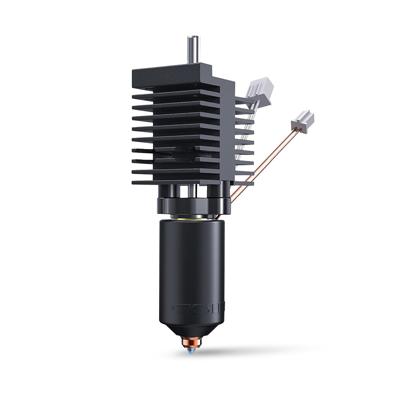
📸 IMAGE PLACEHOLDER: Product shot of Micro Swiss FlowTech hotend and CM2 nozzle packaging
Micro Swiss FlowTech Hotend for Creality K2 Plus
High-performance hotend replacement designed specifically for the K2 Plus
As an Amazon Associate, we earn from qualifying purchases.
ℹ️ Info:
If you are shopping during Q4, keep an eye on the official Micro Swiss website. Using the code BFCM2025 can unlock significant discounts (up to 30%) during Black Friday and Cyber Monday events.
Bench Test: Stock vs. Micro Swiss
Before installation, I performed a side-by-side comparison of the OEM equipment versus the Micro Swiss replacement.
Visual Differences
Stock K2 Plus Hotend
Micro Swiss FlowTech Hotend
Visually, the Micro Swiss unit features significantly larger and more complex cooling fins, suggesting improved thermal management. Interestingly, the heating element section appears slightly smaller on the FlowTech compared to stock.
Weight Comparison
In terms of mass—a critical factor for input shaping calibration—the difference is negligible:
Component
Weight
Stock Hotend
44 grams
Micro Swiss FlowTech
45 grams
This 1-gram difference confirms that the Micro Swiss is effectively a drop-in replacement that won’t drastically alter the toolhead’s mass characteristics. This means your existing input shaping profiles will remain largely valid.
Installation Guide
ℹ️ Info:
Before modifying the toolhead, ensure the printer is unplugged and the power is completely off.
Step 1: Removal
The process begins by carefully unplugging the two connectors attached to the main breakout board. These connectors can be tight, so caution is required to avoid damaging the board headers.
Once disconnected, remove the two retaining screws located near the bottom plate of the hotend assembly.
Step 2: Wiring Orientation
When seating the new FlowTech hotend, proper orientation is vital:
The unit features an indent that must face the front of the printer
Ensure the wires are routed toward the front
Position the brass wire at the top
Getting this orientation correct prevents issues with thermistor readings and ensures proper cooling fan operation.
Step 3: Securing the Unit
With the hotend seated, reinstall the mounting screws:
Loosely thread the front screws first
Then secure the top screws
Final tightening once everything is aligned
This sequence ensures the unit is properly aligned before final tightening and prevents cross-threading or misalignment.
Calibration & Testing
Hardware installation is only half the battle. After powering on the machine, I verified that the thermistor was reporting ambient temperature correctly before attempting to heat the nozzle.
Required Calibration Steps
Because the mass and flow characteristics have changed slightly, users should run the full calibration suite:
PID Tune: To ensure stable temperatures
Input Shaping: To account for the slightly different weight distribution
Auto-Leveling: To adjust for any Z-offset changes
ℹ️ Info:
Check out our complete Klipper Calibration Guide for detailed instructions on running these calibrations.
The ASA Benchy Test
To validate the install, I printed a 3DBenchy using ASA filament.
Results:
✅ Extrusion quality: Excellent, consistent flow throughout
✅ Layer adhesion: Perfect interlayer bonding
⚠️ Bed adhesion: Lifting at the chimney (common with ASA on stock surface)
While the print suffered from a bed adhesion issue—a common struggle with ASA on stock build surfaces—the extrusion quality itself was excellent. The body of the Benchy looked “phenomenal,” confirming that the FlowTech is delivering consistent extrusion.
ℹ️ Info:
For users struggling with ASA adhesion, switching to a dedicated Cryo build plate or textured PEI sheet may be the next logical step. These surfaces provide superior grip for high-temperature engineering filaments.
As an Amazon Associate, we earn from qualifying purchases.
Sponsor: PCBWay
This project is sponsored by PCBWay. Whether you need custom PCB prototyping, CNC machining, or 3D printing services for your next build, PCBWay offers professional-grade manufacturing solutions.
The Micro Swiss FlowTech hotend paired with the CM2 High Flow nozzle represents a meaningful upgrade for K2 Plus owners who:
Print with abrasive engineering materials (carbon fiber, glass fiber, etc.)
Need higher flow rates for large prints
Want improved thermal management
Seek longer nozzle lifespan
The near-identical weight means minimal impact on your existing calibrations, while the hardened steel construction ensures durability for hundreds of hours of printing.
Is It Worth It?
Yes, if you:
Regularly print with abrasive filaments
Push high flow rates with large nozzles
Want to future-proof your hotend investment
Maybe wait if you:
Only print PLA/PETG with standard flow rates
Haven’t experienced issues with the stock hotend
Are on a tight budget
Support Minimal 3DP
If you found this technical guide helpful in navigating your K2 Plus upgrades, consider supporting the channel directly.
YouTube: Subscribe to Minimal 3DP on YouTube for more upgrade guides and technical deep dives.
ℹ️ Info:
This is part of the K2 Plus Upgrade Series. Stay tuned for upcoming guides on:
Installing the hardened extruder gear kit
Upgrading to Klipper firmware
Custom OrcaSlicer profiles for high-flow printing
Disclaimer: This post contains affiliate links. Minimal 3DP may earn a small commission at no extra cost to you, which helps fund future technical deep dives.
Stop Guessing: Introducing the FDM Filament Recommendation Engine
Discover the FDM Filament Recommendation Engine—a data-driven tool that helps you find the perfect 3D printing material for your project by filtering over 40 filaments by strength, printability, UV resistance, and more.
By Mike Wilson |
One of the biggest problems I have in my 3D printing journey is simply trying to remember which filament is best for which scenario. If I need a UV-resistant filament for an outdoor part, or if I need to know if a specific engineering-grade material is actually printable on my current setup, digging through PDF Technical Data Sheets (TDS) takes forever.
To solve this, I’ve developed a new app: the FDM Filament Recommendation Engine.
The goal of this application is to let you sort, query, and filter through over 40 different materials to find the one that fits your specific project needs.
I developed this by analyzing various manufacturer TDS records, but I know those aren’t always perfectly accurate. To validate the data, I also cross-referenced peer-reviewed journal articles. I utilized AI to help extract and organize this massive amount of data into a usable format.
Key Features and Updates
For those of you who saw the early version of this tool, I’ve made several updates based on my own testing and user feedback:
Simplified Strength Metrics
I originally had three different choices for “strength,” but they were all telling me the same thing. I have simplified this to just General Strength and Compressive Strength to make the data easier to read.
Printability Scoring
You can filter by “Printability.” If you back the slider off to an 8, you’ll see familiar materials like PLA and PETG. If you look at engineering materials like PC or ASA, you’ll see that score drop significantly—reflecting the real-world difficulty of printing those materials.
Comparison Tool
This is probably the most useful feature. You can select multiple filaments (for example, UV-resistant materials like ASA, PC, and others) and hit “Compare.” This gives you a side-by-side look at their cost score, heat compatibility, and stiffness.
Processing Data
I’ve added information on whether a material can be annealed—the process of heating the print after printing to make the material stronger and more dimensionally stable.
Feedback Welcome
I have added a feedback form to the site. If you have a better source of data than the TDS sheets or journal articles I have used, please feel free to submit it. My goal is to make this a complete repository of knowledge for us to use.
Sponsor: PCBWay
This project is sponsored by PCBWay. I want to thank them for their continued support of the Minimal 3DP channel.
If you are working on a project that requires custom PCBs, I highly recommend checking out their design services. They have powerful tools on their website to get an instant quote, and their help with PCB design layout starts at just $88.70 US.
Mastering Bed Types in OrcaSlicer: Automate Z-Offsets and Temperatures
Learn how to automate Z-offset and temperature adjustments when swapping build plates using OrcaSlicer’s bed type feature. Perfect for users running multiple PEI sheets or specialized plates.
I found a feature that is incredibly powerful for anyone running multiple build plates on a single printer: specifying bed types.
If you swap between a smooth PEI sheet, a textured plate, or a cool plate, you usually have to manually adjust your Z-offset or run a bed level every time. However, OrcaSlicer allows you to automate this process, saving your Z-offset and temperature settings based on the specific bed you select. For broader slicer tuning, visit the OrcaSlicer Tutorials Hub.
OrcaSlicer generally supports four standard bed definitions: Cool Plate, Engineering Plate, High Temp Plate, and Textured PEI Plate. Even if your specific brand of plate isn’t listed, you can use these presets as placeholders to trigger specific settings.
To enable this feature:
Open OrcaSlicer and go to Printer Settings.
Check the box for “Support multiple bed types”.
Once enabled, you will see a dropdown menu allowing you to select your active bed type directly in the main interface.
Automating Bed Temperatures
One immediate benefit of this feature is temperature management. Different bed materials require different surface temperatures.
For example, I typically use a smooth PEI high-temp plate at 60°C. However, I recently started using the BigTreeTech MENT BQ Cryo Grip ProGlacial beds. These are double-sided (smooth and textured), but they run best about 5 to 10 degrees cooler than standard PEI.
By utilizing the bed type settings in the Filament tab, I can assign specific temperatures to specific plate types (e.g., setting the “Cool Plate” slot to 55°C). This allows me to “set it and forget it”—the slicer handles the temp change automatically based on the bed I select.
Automating Z-Offsets with Start G-Code
The most powerful application of this feature is automating your Z-offset. To make this work, you need to pass the bed type variable from OrcaSlicer to your printer’s start code. After implementing this, refine extrusion consistency using Flow Calibration and ringing reduction with Input Shaping.
1. Update Slicer Start G-Code
In your OrcaSlicer machine start G-code, you need to add a specific variable so the printer knows which bed is selected. The code looks like this:
This line sends the current bed selection to your printer’s configuration. For more macro examples see the Klipper Calibration Hub.
2. Configure Printer Logic (Macros)
Once the printer receives the variable, you can use conditional logic (If/Else statements) in your printer’s configuration (like Klipper macros) to adjust the Z-offset.
Based on examples found on the Creality K2 Plus forums and AI-generated code, the logic works as follows:
Capture the Variable: The macro grabs the uppercase variable CURR_BED_TYPE.
If/Else Statements: The printer checks which bed is active and applies a specific offset.
Example: If using a glass plate, set Z-offset to 0.
Example: If using Textured PEI, set Z-offset to -0.03.
Fallback: You can include an else statement to handle any unknown bed types.
Conclusion
This feature adds a layer of convenience and optimization to your workflow. Whether you are looking to automate temperature changes for Cryo Grip plates or swap between smooth and textured sheets without releveling, specifying bed types in OrcaSlicer is a game changer.
Thanks for stopping by! I’m still recovering, so I appreciate your patience if this wasn’t up to my usual standards, but I look forward to talking to you again soon.
Have questions about your start G-code? Leave a comment on the video!
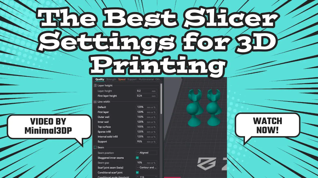
Stop Guessing: I Built a FREE App for Your Best 3D Slicer Settings
Introducing the OrcaSlicer Expert Assistant - a free web app that uses academic research and 130+ manufacturer data sheets to recommend the best slicer settings for your 3D printing goals.
By Mike Wilson |
✅ Success:🎉 NEW FREE TOOL LAUNCH: The OrcaSlicer Expert Assistant is now live at settings.minimal3dp.com
Hey, this is Mike from Minimal3DP.
I’ve had a lot of time to think recently while recovering from heart surgery, and I put that time to use. Today, I want to talk about “the best 3D printer slicer settings” and what that really means.
We’ve all seen videos (even from my own channel) about the “best” settings. But when you open a modern slicer—my choice is OrcaSlicer—you’ll find hundreds, maybe thousands of different settings. The truth is, there is no single perfect setting for every scenario.
What You’ll Learn
✅ Why there’s no “one size fits all” slicer setting
✅ How to use academic research to optimize your prints
✅ How the new OrcaSlicer Expert Assistant works
✅ How to prioritize settings for strength, speed, quality, or accuracy
✅ What 130+ manufacturer data sheets reveal about filament properties
The Problem: Too Many Settings, Not Enough Guidance
Instead of claiming one perfect setting exists, what we’re really doing is optimizing for a specific goal, whether that’s:
Aesthetics and quality - For display models and miniatures
Strength - For functional parts and mechanical components
Flexibility - For parts that need to bend or compress
Surface roughness - For smooth finishes or specific textures
Dimensional accuracy - For parts that must fit together precisely
Each goal requires different settings, and that’s where most tutorials fall short.
My Approach: Using Research, Not Just Opinion
Rather than just giving you my opinion, I’m a big proponent of using Google Scholar. It’s a search engine for academic papers and journal articles. I typically filter my searches to find new articles (e.g., since 2021) to see what parameters affect what properties.
For example, a quick search for “FDM 3D printing process parameters” brings up articles that show exactly how slicer settings impact mechanical properties. I found one article I really like that provides a systematic survey of these parameters and their influence on part characteristics. It has a great diagram showing how settings affect:
Build time
Dimensional accuracy
Surface roughness
Flexural, compressive, and tensile strength
This research is incredibly helpful, but it’s not easy for everyone to parse. So, I started working on a program to help pull these settings from journal articles and give you a clear reference.
Introducing: The OrcaSlicer Expert Assistant
I’m excited to show you what I’ve built: The OrcaSlicer Expert Assistant.
🧮 Try Our Free Calculator
➡️ Try the FREE app now: https://settings.minimal3dp.com No registration required • Works in your browser • Based on real research
First, you select the filament you want to use. This is more than just a name—I’ve fed data from over 130 manufacturer technical data sheets into the app. I used AI to extract all the technical information (strength, heat distortion, glass transition temperature, chemical resistance, etc.) from those PDFs.
This means when you select a material like ABS, the app will give you:
Next, you set your print priority on a scale from 0 (I don’t care) to 100 (max priority) for four key areas:
💪 Strength: For functional parts, tools, and mechanical properties
⚡ Speed: Great for iterating on a design and rapid prototyping
✨ Quality: For display models, miniatures, and aesthetics
📏 Accuracy: Critical for prints that need to fit together
The app understands that these priorities often conflict. For example, maximum speed usually reduces quality. The tool balances these trade-offs based on your priorities.
Step 3: Get Expert Recommendations
Once you hit “Get Expert Recommendations,” the tool analyzes your priorities and the filament data to give you a solid starting point.
Example 1: Dimensional Accuracy Priority
If you set Dimensional Accuracy to 100%:
⚠️ The app will point out that shrinkage is a factor
🐌 Recommend a slower outer wall speed (improves precision)
🕸️ Recommend using the Arachne wall generator (better dimensional control)
📐 Suggest layer height of 0.12 to 0.16mm (optimal for accuracy)
Example 2: Strength + Speed Priority
If you bump up Mechanical Strength and Build Time:
📊 Suggest specific infill patterns (grid or honeycomb for strength)
⚙️ Optimize speeds and acceleration for faster prints
🎯 Balance layer height for strength vs speed trade-off
Built on Real Data, Not Guesswork
What makes this tool different from other “best settings” guides:
✅ 130+ manufacturer technical data sheets analyzed ✅ Academic research from peer-reviewed journals ✅ Systematic approach to parameter optimization ✅ Material-specific recommendations based on properties ✅ Priority-based balancing of conflicting goals
A Good Start, Not a Final Answer
ℹ️ Info:Important: These recommendations are starting points, not final answers. You should still run calibration tests and adjust settings for your specific printer, material batch, and environment.
None of this is “perfect,” but it’s designed to give you a clear idea of how to set your settings in your slicer based on actual research, not just my opinion.
I’m not saying this is the be-all, end-all, but if you’re new to 3D printing and trying to figure out what settings to use, this should be a great start for you.
More Free Tools from Minimal 3DP
If you find the OrcaSlicer Expert Assistant helpful, check out my other free calculators:
FDM Cost Calculator - Calculate true print costs including electricity and time
I did add some affiliate links for different filaments on the side of the app. My hope is that this will help generate a little revenue that I can plow right back into my work for the channel and developing more free tools for the community.
🛒 Use affiliate links when buying filament (no extra cost to you)
Frequently Asked Questions
Q:Is the OrcaSlicer Expert Assistant really free?
A:Yes! The app is 100% free with no registration required. It runs entirely in your browser and doesn’t collect any personal data. I may add affiliate links to filament brands to help support development.
Q:Will this work with other slicers like PrusaSlicer or Cura?
A:Yes! While it’s designed for OrcaSlicer, the principles and most settings translate directly to PrusaSlicer (OrcaSlicer’s parent), Cura, and other FDM slicers. The parameter names might be slightly different, but the concepts are universal.
Q:How accurate are the recommendations?
A:The recommendations are based on peer-reviewed academic research and technical data from 130+ manufacturer data sheets. However, they’re starting points that should be refined through calibration for your specific printer, material batch, and environment. Think of it as an educated starting point rather than a final answer.
Q:What if I have multiple priorities (e.g., both strength AND quality)?
A:That’s exactly what the priority sliders are for! Set each priority from 0-100, and the app will balance the recommendations. For example, if you set both strength and quality to 80, it will find settings that optimize both without sacrificing too much of either.
Q:Which filaments are included in the database?
A:The app includes data for major filament types (PLA, PETG, ABS, ASA, Nylon, TPU, etc.) compiled from 130+ manufacturer technical data sheets. Check my complete filament guide for detailed comparisons.
Q:Can I request new features or report bugs?
A:Absolutely! Please email me at minimal3dp@gmail.com or comment on the YouTube video. I’m actively developing this tool and appreciate all feedback from the community.
Try It Now
Please, check out the app and let me know what you think. If you have any questions, comments, or notice any errors, please let me know.
The Ultimate 3D Printing Filament Guide (2025) - Every Material Tested
Comprehensive guide to the best 3D printing filaments for every application. From PLA to PEEK, find the perfect filament for your next project with honest reviews and recommendations.
Choosing the right 3D printing filament can make or break your project. After years of testing dozens of brands and materials, I’ve compiled this comprehensive guide to help you find the perfect filament for any application.
📺 Watch This Tutorial on YouTube
Want deep-dive tutorials on materials, slicer settings, and real-world tests? Subscribe for long-form guides and honest reviews.
PLA (Polylactic Acid) is the most popular 3D printing filament for good reason: it’s easy to print, doesn’t require a heated bed, and produces minimal odor. Perfect for beginners and decorative prints.
Best Standard PLA
SUNLU PLA 3D Printer Filament
$13.99
Best budget choice. SUNLU’s PLA offers exceptional value with excellent layer adhesion and dimensional accuracy. At under $14/kg, it’s my go-to for everyday printing.
Pros: Affordable, consistent diameter, great color selection Cons: Slightly more brittle than premium brands Best for: Prototypes, decorative prints, learning
As an Amazon Associate, we earn from qualifying purchases.
OVERTURE PLA Filament
$19.99
Premium quality. OVERTURE is known for incredibly consistent diameter control (±0.03mm) and smooth finish. If you need reliability for important prints, this is worth the extra $6.
Pros: Consistent quality, smooth surface, minimal stringing Cons: Higher price point Best for: Final parts, gifts, detailed models
eSUN PLA ($17.99) - B0CS2XHNKL - Reliable basic PLA from a trusted brand
PLA+ (Enhanced Strength)
PLA+ offers significantly better layer adhesion and impact resistance compared to standard PLA, making it ideal for functional parts that need more durability.
eSUN PLA+ Filament
$20.99
The industry standard. eSUN’s PLA+ is the original and still one of the best. Prints like PLA but with 3-4x the impact strength. Perfect bridge between ease-of-use and functionality.
Pros: Excellent toughness, minimal warping, easy to print Cons: Slightly higher printing temperature Best for: Functional parts, tools, fixtures
As an Amazon Associate, we earn from qualifying purchases.
Budget Alternative:
LANDU PLA+ ($17.99) - B0D69RV8W1 - Cost-effective with excellent strength
Specialty PLA
Silk PLA (Metallic Finish)
SUNLU 3D Printer Silk Filament
$19.99
Beautiful silk finish with metallic sheen. Perfect for decorative items, jewelry, and artistic prints. The copper and gold colors are especially stunning.
Tip: Print slowly (40-50mm/s) for best surface finish.
As an Amazon Associate, we earn from qualifying purchases.
Wood-Fill PLA
Creality Wood Filament PLA
$19.99
Natural wood fiber composite with authentic wood texture. Can be sanded and stained like real wood. Great for decorative items, models, and artistic projects.
Tip: Vary temperature (190-220°C) during print to create wood grain effect.
As an Amazon Associate, we earn from qualifying purchases.
Carbon Fiber PLA
ELEGOO Carbon Fiber PLA Filament
$24.99
Carbon fiber reinforced PLA for enhanced rigidity. Excellent dimensional stability and a premium matte finish. Warning: Use hardened steel nozzle to prevent wear.
Best for: Drone parts, RC car components, rigid structures
As an Amazon Associate, we earn from qualifying purchases.
PETG Filaments
PETG combines the ease of PLA with the strength of ABS. It’s my top choice for functional parts that need durability without requiring an enclosure.
OVERTURE PETG 3D Printer Filament
$21.99
Best all-around PETG. OVERTURE’s PETG offers excellent layer adhesion, minimal warping, and good chemical resistance. Perfect for mechanical parts, containers, and outdoor items.
Print Settings: 235-245°C hotend, 70-80°C bed Pros: Strong, flexible, chemical resistant Cons: Can be stringy (use retraction tuning) Best for: Mechanical parts, containers, outdoor items
As an Amazon Associate, we earn from qualifying purchases.
Budget Options:
SUNLU PETG ($18.99) - B0DJS3PJVX - Reliable quality at best price
Creality PETG ($19.99) - B0C8NP63GD - Strong and flexible
ABS & ASA Filaments
For parts requiring heat resistance and durability, ABS and ASA are your go-to materials. Requires enclosure to prevent warping.
ABS (Acrylonitrile Butadiene Styrene)
Polymaker ABS Filament
$29.99
Premium ABS with minimal warping. Polymaker’s formula is easier to print than standard ABS and produces less odor. Excellent for automotive parts and functional components.
As an Amazon Associate, we earn from qualifying purchases.
ASA (UV-Resistant Alternative to ABS)
Polymaker ASA Filament
$29.99
Best for outdoor use. ASA has excellent UV resistance (won’t fade or degrade in sunlight) while maintaining ABS’s strength and heat resistance. Perfect for outdoor fixtures, signs, and garden items.
Why ASA > ABS for outdoors: Won’t yellow or become brittle from UV exposure Best for: Outdoor fixtures, automotive trim, signage
As an Amazon Associate, we earn from qualifying purchases.
TPU Flexible Filaments
Flexible filaments open up entirely new applications. Print phone cases, seals, gaskets, and flexible parts.
OVERTURE TPU Filament (95A)
$23.99
Best TPU for beginners. 95A hardness offers good balance between flexibility and printability. Works on most direct drive printers without modifications.
Engineering-grade material with excellent mechanical properties. Hygroscopic - requires dry box or dryer.
OVERTURE Nylon Filament
$27.99
Strong and flexible nylon for mechanical parts. Excellent wear resistance and low friction coefficient make it perfect for gears, bushings, and living hinges.
Print Settings: 250-270°C hotend, 70-80°C bed, must keep dry Best for: Gears, bushings, mechanical parts, living hinges
As an Amazon Associate, we earn from qualifying purchases.
Specialty Materials
High-Temperature PLA (HT-PLA)
Polymaker HT-PLA-GF Filament
$25.49
Heat-stabilized PLA+ with enhanced temperature resistance. Can withstand temps up to 90°C after annealing. Prints like PLA but performs like engineering plastic.
Process: Print normally, then anneal at 100°C for 1 hour in oven Best for: Functional parts, automotive, under-hood applications
As an Amazon Associate, we earn from qualifying purchases.
Polycarbonate (Maximum Impact Resistance)
Polymaker Polycarbonate Filament
$39.99
Virtually unbreakable. PC is used for bulletproof glass and riot shields. Excellent for protective cases, safety equipment, and impact-resistant parts.
As an Amazon Associate, we earn from qualifying purchases.
Alternative:
Polymaker PVA ($34.99) - B09KL8WBRY - Premium quality for critical prints
Essential Accessories
Filament Dryer (Critical for Nylon, PETG, PVA)
Creality Official Filament Dryer Box
$39.99
Efficient filament dryer with adjustable temperature. Essential for hygroscopic materials like Nylon, PETG, and PVA. Prevents moisture-related print issues.
Critical: Must store in dry box, dry before printing
TPU
Temperature: 220-230°C (hotend), 40-60°C (bed)
Speed: 20-30mm/s (slow!)
Cooling: 0-50%
Recommended: Direct drive extruder
Storage & Maintenance
Keep Filament Dry:
Store in sealed bags with desiccant
Use filament dry box for hygroscopic materials (Nylon, PETG, PVA)
Dry before printing if absorbed moisture
Signs of Wet Filament:
Popping/crackling sounds during extrusion
Excessive stringing
Poor layer adhesion
Brittle prints
Drying Guide:
PLA: 45-50°C for 4-6 hours
PETG: 60-65°C for 4-6 hours
Nylon: 70-80°C for 8-12 hours
PVA: 45-50°C for 4 hours
Frequently Asked Questions
Q: What’s the best filament for beginners? A: Standard PLA. It’s affordable, easy to print, and doesn’t require a heated bed. Start with SUNLU PLA ($13.99) for best value.
Q: Can I print PETG without an enclosure? A: Yes! PETG prints well without enclosure, unlike ABS/ASA. Just use 70-80°C bed temp and minimal cooling.
Q: Do I need a special nozzle for carbon fiber filaments? A: Yes, hardened steel nozzle is essential. Brass will wear out quickly from abrasive CF particles.
Q: How long does filament last in storage? A: PLA/PLA+: 1-2 years if kept dry. PETG/Nylon: 6-12 months. Always use desiccant in storage.
Q: Why is my nylon print brittle? A: Most likely moisture absorption. Dry your nylon for 8-12 hours at 70-80°C before printing.
Q: Can I mix brands/materials? A: Yes for same material type (different PLA brands work fine together). No for different materials in same print without proper interface settings.
Conclusion
Choosing the right filament depends on your specific application:
Just starting out? SUNLU PLA ($13.99)
Need strength? eSUN PLA+ ($20.99)
Functional parts? OVERTURE PETG ($21.99)
Outdoor use? Polymaker ASA ($29.99)
Flexible parts? OVERTURE TPU ($23.99)
Engineering? Nylon or Nylon CF
Remember: The “best” filament is the one that meets your specific needs at the right price point. Don’t overspend on engineering materials for decorative prints, but don’t compromise on quality for functional parts.
Have questions about which filament is right for your project? Drop a comment below and I’ll help you choose!
This post contains affiliate links. As an Amazon Associate, I earn from qualifying purchases at no cost to you. All recommendations are based on personal testing and experience.
M3DP 3D Print Cost Calculator
This tool is designed to help you capture all those hidden costs and generate a detailed quote for your 3D prints, which you can save for your own records or print as a PDF to send to a customer
If you’ve ever thought about selling your 3D prints, one of the first and biggest hurdles is figuring out how to price them accurately. Most people just look at the material and electricity costs, but that’s a quick way to lose money.
I recently read an article called “Refined Cost Calculation Framework for FDM Parts,” which breaks down the entire cost process into much greater detail. It factors in everything:
Machine costs and energy
Tooling costs (like nozzle wear and build sheet lifespan)
Material and model costs
Labor costs (for setup, slicing, and post-processing)
This model is far more accurate, but the one major problem is that with so many inputs, it’s incredibly hard to keep it all straight.
I started building a spreadsheet to manage this for myself, and… well, it turned into a full-blown web tool.
Introducing the M3DP 3D Print Cost Calculator
I’ve created a 3D Print Cost Calculator that’s now live on my website. You can find it under the “M3DP Tools” menu item.
This tool is designed to help you capture all those hidden costs and generate a detailed quote, which you can save for your own records or print as a PDF to send to a customer.
In it, you can dial in specific parameters for:
Labor: Set your own hourly rate for slicing, machine setup, and post-processing.
Machine: Input your machine’s cost and estimated lifespan in hours.
Components: Add costs and lifespans for your nozzle and build plate (I found research suggesting a PEI sheet can last 5,000+ hours!).
Failure Rate: Add a percentage to help cover the cost of failed prints.
Markup: Add a final markup to the total calculated value.
One of the most important features: everything is saved 100% client-side. It all stays on your machine; nothing is saved to my server. You can even save and load different setting profiles.
Watch the Full Walkthrough
I put together a video walking through the entire calculator, using a real-world part as an example. I show you where to find the tool, how to pull the data from your slicer, and how to fill out every field.
This tool is brand new, and I’m still testing it and adding features.
Please check it out, give it a try, and let me know what you think. If you see any errors, have suggestions for new features, or think of any costs that I’m not currently capturing, please let me know in the video comments or contact me through the site.
Hopefully, this helps you price your prints more accurately and professionally. I look forward to hearing what you think!
References
The methodology for this calculator was based on the concepts presented in the following research, which is also referenced within the tool itself:
Component Research: The tool also incorporates research findings for the average lifespan of components like nozzles and build plates.
OrcaSlicer 2.3.1 Alpha Just Dropped & How to Use the New Flow Rate Calibration
This guide provides a deep dive into the new Archimedean flow calibration feature in OrcaSlicer 2.3.1 Alpha, which replaces subjective guesswork with a visually precise test. Follow our step-by-step instructions to interpret the results and perfectly dial in your filament’s flow rate for higher quality 3D prints.
Mastering Extrusion: A Deep Dive into OrcaSlicer’s New Archimedean Flow Calibration
From Subjective Guesswork to Visual Precision: A Step-by-Step Guide to Perfecting Your Flow Rate with the OrcaSlicer 2.3.1 Alpha Feature
The Next Evolution in Slicing: Introducing OrcaSlicer 2.3.1 Alpha
The Relentless Pursuit of Perfection
If you’re like me, you’re constantly on the lookout for the latest and greatest features to elevate your 3D prints from good to flawless.1 This relentless pursuit of perfection is the lifeblood of the 3D printing community, and it’s a spirit embodied by the team behind OrcaSlicer. More than just a piece of software, OrcaSlicer has established itself as a dynamic, open-source project at the vanguard of Fused Deposition Modeling (FDM) technology.2 It’s a slicer built by and for the community, characterized by a rapid development cycle that consistently delivers powerful, cutting-edge tools into our hands.
It is in this spirit of continuous innovation that the developers have released OrcaSlicer version 2.3.1 Alpha.1 This isn’t just a minor update; it’s a significant leap forward, offering an exciting glimpse into the future of slicing. This release is packed with enhancements that promise to refine our workflows and improve our print quality in tangible ways.
A Glimpse of the Future: What’s New in Version 2.3.1 Alpha?
The 2.3.1 Alpha release is a treasure trove of new functionalities that address various aspects of the printing process. While this guide will focus on one revolutionary feature, it’s worth taking a moment to appreciate the breadth of improvements included in this update.1 The key additions are:
A new sparse infill rotation system for stronger, more efficient internal structures.
Substantial changes and improvements to the fuzzy skin feature, offering more creative control over surface textures.
Integrated input shaping calibration for printers running Klipper firmware.
A new junction deviation calibration test for users with Marlin-based machines.
And, the focus of our deep dive today, a completely redesigned and more intuitive method for flow rate calibration.1
Each of these features deserves its own detailed exploration, and I plan to cover them in future articles and videos. However, the new flow calibration method represents such a fundamental shift in approach and offers such a significant improvement in accuracy and ease of use that it warrants a dedicated, comprehensive guide. My goal here is to provide a focused, exhaustive walkthrough that will empower you to master this new tool immediately, without wasting your time.1
Multimedia Integration: Watch the Guide in Action
For those who prefer a visual demonstration, I have created a complete video walkthrough that complements this written guide. You can watch it to see the entire process in action, from launching the test in OrcaSlicer to analyzing the physical prints.
The Philosophy of Alpha Releases in Open Source
Before we dive into the technical details, it’s important to understand the context of an “Alpha” release. In the world of open-source software, an alpha version is far more than just an early, potentially unstable preview. It represents a philosophical choice that lies at the heart of community-driven development.2 Unlike the closed, internal testing of proprietary software, a public alpha is a transparent invitation for the most engaged users to become active participants in the development process.
The OrcaSlicer project thrives on this collaborative model, offering not just stable releases but also “Nightly Builds” for those who want to test the absolute latest code.2 When you download and use OrcaSlicer 2.3.1 Alpha, you are not merely a consumer; you are a collaborator. The feedback you provide, particularly through well-documented bug reports, is invaluable data that helps the developers refine, debug, and perfect these new features before they are rolled into a stable release.1 This guide will not only show you how to use the new flow calibration but also how to responsibly contribute back to the project that provides these powerful tools for free.
From Subjective Feel to Objective Data: A Paradigm Shift in Flow Calibration
The Old Way: Limitations of the Diagonal Surface Test
To fully appreciate the brilliance of the new flow calibration method, we must first understand the limitations of the one it replaces. For a long time, flow rate calibration in OrcaSlicer (and many other slicers) involved printing a series of square patches, each with a different flow modifier.[4, 5] The top surface of these squares was printed with a simple diagonal line pattern, moving back and forth at a 45-degree angle.1
The process for determining the correct flow rate was almost entirely subjective. The official instruction was to run your fingers across the printed squares and select the one that felt the smoothest to the touch.1 While this method can work, its effectiveness is heavily dependent on the user’s experience and tactile sensitivity. A beginner might struggle to discern the subtle differences between patches, while even an expert’s judgment could be influenced by lighting or the specific texture of the filament. This subjectivity was the primary weakness of the old system, creating a barrier to achieving consistent, repeatable results.
Introducing the Archimedean Chord: A Smarter Pattern for a Smarter Slicer
The 2.3.1 Alpha release replaces the ambiguous diagonal pattern with a far more intelligent design: a concentric pattern based on an Archimedean chord.1 This isn’t just a cosmetic change; it’s a fundamental re-engineering of the test based on geometric principles.
An Archimedean spiral is a shape defined by a path that moves away from a central point at a constant angular velocity. In simpler terms, the distance between each successive turn of the spiral remains constant. When the toolhead of a 3D printer traces this path, it should lay down a series of perfectly concentric lines with a uniform gap between them. This geometric purity is the key to the test’s effectiveness. Any deviation from the ideal amount of extruded filament—either too much or too little—will immediately disrupt this perfect, repeating pattern in a way that is visually and tactically obvious.
Unlike the old diagonal pattern, where over-extrusion might simply result in a slightly rougher surface, the Archimedean pattern provides clear, unmistakable evidence. This new test, as highlighted in the updated OrcaSlicer wiki, is now the recommended method for dialing in your flow rate.1
The Democratization of Precision
This evolution from a tactile, experience-based method to a visually explicit one represents more than just a technical upgrade; it’s a move that democratizes precision in 3D printing. It effectively lowers the barrier to entry for achieving one of the most critical calibrations, empowering users of all skill levels to diagnose and resolve extrusion issues with a newfound level of confidence.
The old method relied on an acquired skill—a developed “feel” for surface smoothness that created a knowledge gap between newcomers and seasoned veterans.1 The new test replaces this subjectivity with objective, observable data. Over-extrusion presents itself as distinct ridges where “the edge of the circle is really sticking out,” while under-extrusion creates clear “valleys” or gaps between the lines.1 These are not matters of opinion; they are measurable physical artifacts.
This aligns perfectly with OrcaSlicer’s overarching mission: to package “advanced calibration tools” within a “user-friendly interface” that supports a “wide printer compatibility”.2 By making a foundational calibration process like flow rate easier to perform and more reliable to interpret, the software empowers a much broader range of users to achieve superior print quality. It removes the gatekeeper of subjective “feel” and replaces it with the clarity of visual evidence. This new feature is a perfect encapsulation of the project’s philosophy: it doesn’t just add power for experts; it engineers that power in a way that elevates the entire community.
A Practical Guide: Dialing in Your Flow Rate with the New Test
Prerequisites and Setup
Before you jump into printing the new calibration test, a little preparation will ensure you get the most accurate results possible.
First, this test is designed to refine an existing flow rate, not to establish one from absolute zero. It is most effective when you start with a filament profile that is already reasonably well-configured. The calibration test works by applying small positive and negative modifiers to your filament’s current flow ratio setting. As the transcript notes, “it doesn’t reset it back to one. It’s based on what it’s currently set at”.1 So, if your filament profile’s flow ratio is already set to 0.98, the test chips will be modifiers based on that value.
Second, for the most scientifically accurate calibration, it’s crucial to follow the recommended order of operations. According to the official OrcaSlicer wiki, you should always calibrate temperature before calibrating flow rate.4 The temperature of your nozzle directly affects the viscosity of the filament, which in turn impacts how it flows. Dialing in your temperature first ensures that you are calibrating flow under the correct thermal conditions.
Step 1: Launching the Calibration Test
With your slicer open and your printer profile selected, launching the new test is straightforward.
Navigate to the top menu bar.
Click on the “Calibration” dropdown.
Select “Flow Rate.” A new test plate will be automatically generated in your workspace.
You will see a series of small, square chips laid out on the build plate. Each chip is labeled with a modifier value, such as 0, -0.01, +0.01, etc. This is the new, recommended test that utilizes the Archimedean pattern.1
Step 2: Printing and Initial Observation
Once the test plate is generated, simply slice it using the filament profile you wish to calibrate and send it to your printer. While it’s printing, prepare a well-lit area for inspection. Good lighting is critical for visually identifying the subtle surface differences between the test chips.
Step 3: Interpreting the Print – The Art of Sight and Touch
This is the most critical part of the process. Once the print is finished and has cooled, carefully remove it from the build plate. You will now analyze each chip, using both your eyes and your fingertips, to find the one that represents the “Goldilocks” zone of perfect extrusion.
Identifying Over-extrusion
Over-extrusion occurs when the printer pushes out too much filament. On the Archimedean pattern, this is incredibly easy to spot.
Visual Cues: Look for concentric circles where the edges are raised and pronounced. As the transcript describes, “the edge of the circle is really sticking out”.1 This happens because the excess plastic has nowhere to go and is forced upwards, creating distinct ridges. The surface may look overly glossy and lose fine detail.
Tactile Cues: When you run your finger across an over-extruded chip, it will feel bumpy and rough. You will be able to clearly feel the ridges formed by the excess filament. The chips with positive modifiers (e.g., +0.03, +0.05) are most likely to exhibit these characteristics.
Identifying Under-extrusion
Under-extrusion is the opposite problem: the printer is not pushing out enough filament to fill the toolpath completely.
Visual Cues: Look for visible gaps between the concentric lines. You may be able to see the layer below through these gaps. The transcript refers to these as “valleys” in the surface.1 The surface might also have a dull, matte, or unfinished appearance because the lines are not properly squishing together.
Tactile Cues: An under-extruded chip will feel textured or even hollow. Your finger will catch on the gaps between the lines, giving it a rough or scratchy feel. The chips with negative modifiers (e.g., -0.03, -0.05) are the primary candidates for this issue.
The “Goldilocks” Zone – Identifying the Optimal Result
Your goal is to find the single chip that is perfectly smooth, both visually and by feel.1
The Ideal Chip: The best chip will have a uniform, smooth top surface with a consistent, healthy shine.1 The concentric lines should be laid down perfectly next to each other with very little to no visible gaps. When you run your finger across it, it should feel almost like a single, solid surface. In my own testing for the video, the chip labeled 0 was the best, indicating my existing flow rate was already well-calibrated.1
An Important Nuance: It is crucial to understand one key detail from the official documentation: “it is okay to have a visible line between the inner and outer spiral”.1 The goal is not to create a completely fused, monolithic surface where the lines are indistinguishable. The perfect result is one that shows distinct lines laid down with “very little gap between” them.1 Do not mistake the faint line between toolpaths for under-extrusion. You are looking for the smoothest possible surface that is free of ridges (over-extrusion) and significant valleys (under-extrusion).
Step 4: Applying the Results and Updating Your Profile
Once you have identified the best chip, updating your filament profile is incredibly simple. The value printed on the chip is the exact modifier you need to apply to your current flow ratio.
The logic is simple addition or subtraction:
If you picked a chip with a positive value (e.g., +0.02), you add that value to your current flow ratio.
If you picked a chip with a negative value (e.g., -0.03), you subtract that value from your current flow ratio.
If you picked the 0 chip, no changes are needed.
Let’s use the concrete example from the transcript: imagine your filament’s flow ratio was set to 0.98 and you determined that the chip labeled +0.01 was the smoothest. Your new flow ratio would be $0.98 + 0.01 = 0.99$.1 This direct arithmetic is a significant improvement in user experience over older, more complex percentage-based formulas.[4, 5]
To make the change in OrcaSlicer:
Go to the “Filament” tab in the left-hand panel.
Click the “Edit preset” icon next to your chosen filament profile.
In the filament settings window, scroll down until you find the “Flow Ratio” parameter.
Enter your newly calculated value.
Crucially, click the “Save” icon at the top of the window to save your changes to the profile. Forgetting this last step is a common mistake that will cause you to lose your newly calibrated value.
The Enabler’s Guide: Responsible Use of Alpha Software
You Are Now Part of the Development Team
Choosing to use alpha software is choosing to step onto the front lines of development. It’s a decision that reframes your role from a passive user to an active tester and contributor. Every print you run, every setting you tweak, provides real-world data that is impossible to replicate in a controlled lab environment. By engaging with these new features early, you are providing an invaluable service to the developers and the entire OrcaSlicer community. You are helping to forge the tools that everyone will be using in the next stable release.
How to Submit an Effective Bug Report: A Checklist
Finding a bug in alpha software is not a failure; it’s a success. It’s an opportunity to contribute directly to the project’s improvement. However, the usefulness of your discovery depends entirely on the quality of your bug report. A vague or incomplete report is often unusable. To help you make the most impactful contributions, here is a checklist for submitting an effective bug report on the OrcaSlicer GitHub page, based directly on best practices.1
Step
Action
Why It’s Important
1
Search First
Go to the OrcaSlicer GitHub “Issues” page and search to see if your bug has already been reported.
2
Provide Context
State the exact OrcaSlicer version (e.g., 2.3.1 Alpha), your Operating System (e.g., Windows 11, macOS Sonoma), and OS version.
3
Document Steps
Write a clear, numbered list of the exact steps required to reproduce the error. Be as specific as possible.
4
Include Your Setup
Mention the specific 3D printer profile you are using (e.g., Voron 2.4, Bambu Lab X1C, Creality Ender 3).
5
Add Visuals & Logs
Attach screenshots that clearly show the issue. If the slicer crashes, include the debug log file it generates.
The Power of Community Feedback
A well-structured bug report is one of the most powerful contributions a user can make to an open-source project. It transforms a moment of frustration into a constructive step toward a more robust and reliable piece of software for everyone. Despite its “Alpha” status, my own experience with version 2.3.1 has been that it “seems rock solid,” a testament to the quality of the developers’ work and likely the result of excellent community feedback during the nightly build phase.1
Conclusion, Community, and Further Resources
Summary: A Step Forward for Precision
The introduction of the Archimedean chord flow calibration in OrcaSlicer 2.3.1 Alpha is a definitive step forward for precision 3D printing. By replacing a subjective, tactile test with a visually objective and geometrically intelligent one, OrcaSlicer has made a critical calibration process more accessible, repeatable, and accurate for users of all experience levels. It is a smarter test for a smarter slicer, and a perfect example of the thoughtful innovation that defines the project.
Join the Conversation: A Call to Action
Your experience and feedback are what make the 3D printing community thrive. Now that you’ve learned about this new feature, I encourage you to join the conversation.
Have you tried the new flow test? What were your results? Is there another new feature in the 2.3.1 Alpha release that you feel I should highlight in a future guide? As I always say, “just leave me a comment and I’ll get back to you as soon as I can”.1
If you found this guide valuable, please consider giving it a few ‘claps’ here on Medium. This is a simple, free way to show your support, and it helps the platform’s algorithm show this article to more people who might benefit from it.
For more deep dives, tutorials, and the latest updates in 3D printing and OrcaSlicer, be sure to subscribe to my YouTube channel and follow me here on Medium.1
The OrcaSlicer Ecosystem: References and Further Reading
To continue your journey and become more involved with the OrcaSlicer project, here are the essential official resources. I strongly recommend bookmarking these to ensure you are always getting information from the primary source.
Official OrcaSlicer GitHub Repository: This is the home of the project. Here you can download the latest stable and alpha releases, read the full release notes, and report bugs.2
Official OrcaSlicer Wiki: An invaluable resource for detailed documentation on all of OrcaSlicer’s features, including the main Calibration page which provides a broader overview of the entire tuning process.4
Official OrcaSlicer Discord Server: The best place to engage with the community in real-time, ask questions, and get support from fellow users and the developers themselves.2
Finally, I want to extend a heartfelt thank you to all of my subscribers and members. Your support is what makes it possible for me to create in-depth content like this guide. Thank you for being a part of this community.1
Level Up Your Prints: Why Line Width is Your 3D Printing Secret Weapon
Level Up Your Prints: Why Line Width is Your 3D Printing Secret Weapon
Hey everyone! In my latest video, I dove deep into a 3D printing setting that often gets overlooked but makes a massive difference in your final prints: line width. For a long time, I was all about chasing faster print times, but I’ve come to realize that optimizing for quality and strength is well worth a few extra minutes – and line width is a key player in achieving just that [00:35].
What I Learned (and You Should Too!):
One of the biggest takeaways for me was just how much line width impacts the strength of your parts. Think about it: wider lines mean more material is laid down and there’s greater overlap between those lines, especially when it comes to printing walls. This significantly reduces those annoying little voids and makes your prints much more structurally sound [01:25], [03:06].
In the video, I specifically explored the line width settings within Orca Slicer. It’s pretty cool how much control you have, with options for the default width, the first layer, outer walls, and even the top surface [01:38].
Through my research (and a bit of trial and error!), I found that for a standard 0.4mm nozzle, bumping up the default line width to around 0.5mm (that’s 125%) seems to be a sweet spot. This aligns with recommendations in the Orca Slicer wiki and what others in the community are finding [05:10].
The best part? I was genuinely surprised at how little impact these adjustments had on the overall print time. The test print I showed in the video only took about 7 seconds longer with the optimized settings [10:06]. That’s a tiny trade-off for a noticeable improvement in quality!
Speaking of quality, I was really happy with how much cleaner the top surface looked after making these changes. You could see a real difference in how those layers blended together, resulting in fewer visible lines [11:22].
Oh, and here’s a little bonus tip I shared in the video: if you’re struggling with removing support material, try using a slightly thinner line width (smaller than your nozzle diameter) for your support structures. It makes them much easier to break away [08:37].
Give it a Shot!
Ultimately, what I wanted to show in this video is that taking the time to dial in your line width settings is well worth the effort. It’s all about finding that balance between print speed, the quality of your finished product, and the overall strength of your 3D prints [12:33].
Check out the full video for a more in-depth look and to see the results for yourself!
Let me know in the comments what line width settings you’ve found work best for you – I’m always learning! What else are you curious about in the world of 3D printing?
Finding Your 3D Printer’s Sweet Spot - A Guide to Maximizing Print Speed
Have you ever wondered how fast your 3D printer can truly go? When I get a new printer or see a new model released, the first question that pops into my head is always, “How fast can I print with this thing?”
This post will explore how to determine the optimal print speed for your 3D printer, ensuring both speed and quality.
Factors Influencing Print Speed
Print Parameters
Infill: While not a major time-saver, adjusting infill patterns and density can slightly reduce print time.
Wall Thickness: Reducing the number of walls can significantly decrease print time, but it can also compromise the model’s strength.
Layer Height: Increasing layer height generally speeds up printing, but it can also affect print quality and part strength.
Other Parameters: Factors like print speed, infill density, and layer height also impact the mechanical properties of the printed part, according to research. Finding the balance between speed and strength is crucial.
Extruder Limitations
Max Flow Rate: Each extruder has a maximum flow rate, which determines how much filament it can push out per second. Exceeding this limit leads to inconsistent extrusion, poor print quality, and weaker parts.
Determining Max Flow Rate
Ellis’s Print Tuning Guide provides valuable information and equations to calculate your extruder’s max flow rate. A simple test involves extruding a known length of filament at increasing speeds until you observe a noticeable drop in extrusion quality.
One of the key points that Ellis’ guide points out is that using approximate values (Table 1) is possible.
Hotend
Flow Rate (mm3/s)
E3D V6
11
E3D V6 Volcano
20
E3D Revo
11
Dragon SF
15
Sailfish
20
Dragon HF
24
Dragonfly BMO
13
Rapido HF
24
Rapido UHF
30
Mosquito
20
Mosquito Magnum
30
Bambu X1
35
Finding the Sweet Spot
Determine Max Flow Rate: Conduct tests as described above to find your extruder’s maximum volumetric flow rate.
Set Volumetric Speed: Adjust the volumetric speed setting in your slicer software to match your calculated max flow rate.
Optimize Print Profiles: Experiment with different print speed settings for various parts of the model, ensuring that the speeds for visible features do not exceed the calculated safe limit.
Test and Iterate: Print test parts and adjust parameters based on the results. Observe print quality, part strength, and overall print time.
Important Considerations
Model Size: Smaller models may not allow the printer to reach maximum speed due to acceleration and deceleration times.
Part Complexity: Complex models with intricate details may require slower print speeds to ensure accurate and high-quality results.
By carefully considering these factors and conducting thorough testing, you can optimize your 3D printer’s print speed while maintaining excellent print quality and part strength.
Disclaimer: This information is for general guidance only. Always refer to your printer’s manual and manufacturer’s recommendations for specific instructions and safety guidelines.
I hope this guide helps you unlock your 3D printer’s full potential!
This Week on Minimal 3DP (April 28)
This week I am continuing work on my Voron 2.4. I will be adding to my Orca Slicer tutorials as I can as well.
i recordedcan unboxing video on Sunday and I have begun building the Voron this week. I am working myvway through the assembly manual and wiol drop a vireo of rrame assembly next weekend.
Orca Slicer Tutorials
I am working to add to my Orca Slicer tutorials th ok s week. i want to do a post on ideal settings for support (based on a viewer question) and do a video on my recommendation for seam settings.
STEM Outreach
As part of my job, I sometimes do STEM outreach with local schools. This usually involves taking a 3D printer and talking to kids (and parents) about STEM careers. Before I go to an event, I have gotten into the habit of 3D printing a bunch of print-in-place and flexi animals to give out. This week I am hoping to print 100 animals.
This Week on Minimal 3DP (April 21)
I am getting ready to start a new project this week. I am building a Voron 2.4 Pro+
I have started getting together my project website for my Voron build. One of the newer ideas I am trying is to create a project website. I am hoping that it makes it easier for me to save references and other links. I typically try to research a project before I begin and it will make it to asier to share my research.
With the Voron build, I have mostly saved basic references from the Voron site. I have also saved doc from the FormBot site. They appear to have some updated instructions for their kits.
Belt Driven Ender 3
I stumbled across this project a while ago. It seemed like an interesting conversion for my Ender 3 v2. This week I am going to work on adding a project website and printing the needed parts. The hardware cost less than $30 USD.
STEM Outreach
As part of my job, I sometimes do STEM outreach with local schools. This usually involves taking a 3D printer and talking to kids (and parents) about STEM careers. Before I go to an event, I have gotten into the habit of 3D printing a bunch of print-in-place and flexi animals to give out. This week I am hoping to print 100 animals.
Klipper Calibration Website
The Klipper Calibration Website is a series of tools and calculators to help you tune and optimize Klipper and your 3D prints.
M3DP Tools and Connections
Photo: Mike Wilson / CC-BY-CA
A while ago, I create the my Klipper Calibration Spreadsheet to help myself keep track of and remember various Klipper formulas to tune and improve my 3D prints. I decided to share the tools and i have received lots of requests to share the Spreadsheet. Rather than giving everyone access to edit my original sheet, I have recommended to everyone to “Make a Copy” of the sheet for their personal use. In a lot of cases this has caused some confusion. By making a copy, there is no way to any edits or updates I do to the tools.
Because of this (and my desire to do a little programming), I have put together the Klipper Calibration Website. The standalone site gives me an opportunity to create some useful tools and program. It also give me a way to create more detailed documentation and video links.
Another hope is that, because I am using Docsy, I can use the tie-ins with GitHub to allow the community to comment, make suggestions, and give feedback. I could than further refine the tools. It is my hope that this site will continue to evolve over time and include additional tools.